
AIR BRAKE
Competition from other form of transport has warranted the Railways to run trains at higher speed, heavier load etc. to achieve this better and reliable braking is required. The vacuum brake has got its own limitations like brake fading, increased application and release timings etc., in practice it is not reliable to run trains in higher altitudes due to insufficient vacuum levels in brake van and train engine. Hence to overcome the above problems, it has become necessary to introduce Air brake system to control the speed of the train and to stop it within a reasonable distance, irrespective of length, load of the train, distance covered and altitude of the train.
Advantages of Air brake over Vacuum brake system
Uniform brake power is possible throughout the train in air brake, but it is not possible in case of vacuum brake, since the pressure drop at the rear of the train is up to 20%. The propagation rate of compressed air is 260 m/sec to 280 m/sec. when compared to 60 to 80 m/sec. in the case of vacuum brake. The Air brakes have potentiality to run trains longer than 600 metres length. The air brake trains have potentiality to run heavier trains than 4500 tons, Shorter braking distance, Suitable for higher altitudes, Compact and Easy to maintain, Consumption of spare parts is very less, Simple brake rigging, Quicker application and release, so 166 better punctuality can be achieved, Better utilisation of rolling stock since less maintenance and pre departure detention.
Differences between Air Brake and Vacuum brake


6.1 Types of Air Brake System
There are two types of air brakes namely;
- Direct release (Mainly used on American Rail Road)
- Graduated Release (Used on Indian Railways)
Direct release system
In direct release system the brake cylinder pressure cannot be reduced in steps by increasing the brake pipe pressure in steps during release. The brakes are released immediately, as soon as releasing of brake is initiated.

Graduated release system:
In this system the brake cylinder pressure can be reduced gradually in steps in proportion to the increase in brake pipe pressure.


The inherent inexhaustibility feature in Graduated release system facilitates in locking of air pressure in the brake cylinder, during brake application. This helps the driver to control the train effectively over gradients irrespective of repeated brake application. Hence it is preferred in Indian Railways due its topography.
Note: In both the types brake application is directly proportional to the reduction in brake pipe pressure.
The Air Brake System is further classified into;
1. Single pipe air brake system.
2. Twin pipe air brake system.
Single pipe system: There is only one pipe called brake pipe running from loco to the brake van in order to get continuity of air for the application and release of brakes.
Twin pipe system: In addition to the brake pipe, there is one more pipe called feed pipe, running from loco to the brake van to charge the auxiliary reservoir continuously to 6 Kg/Cm2.
6.2 Components of air brake equipment

Distributor Valve assembly
The distributor valve assembly consists of a valve body, a common pipe bracket, and a control reservoir. All the pipe connections from brake cylinder, auxiliary reservoir and brake pipe are connected to distributor valve through the common pipe bracket. The pipe bracket remains on the wagon/coach when the distributor valve is removed for overhaul and maintenance without disturbing the pipe connections. The control reservoir is directly connected to distributor valve through common pipe bracket. An isolating cock is provided either on the distributor valve or on the adaptor to isolate the distributor valve when found defective. A manual release valve is provided at the bottom of the distributor valve by which the brakes in a particular vehicle can be released manually by pulling the handle.
Brake Cylinder
The brake cylinder receives compressed air from auxiliary reservoir after being regulated by the distributor valve and converts to mechanical brake power by outward movement of its piston assembly. The compression spring provided in the brake cylinder brings back the rigging to its original position when brake is released.
Different sizes of Brake Cylinders

Cut-off Angle Cock
Cut off angle cocks are provided on either ends of the brake pipe and feed pipe. These cocks are used at the time of uncoupling of wagons/coaches. This has a vent feature. Once the cock is closed it allows the air trapped in the air hose to atmosphere. When MU washer or hose assembly itself has to be changed, the cut off angle cocks are closed which in turn isolates the brake/feed pipe from further charging and allows the entrapped air in the hose to flow out, to carry out the repairs safely. It also serves as dummy for the rear of the wagon/coach and the front of engine. When the handle is parallel to the pipe the cock, it is in open position and when at right angles to the pipe, it is in closed position.
Control Reservoir
Control reservoir is mounted on the common pipe bracket. It always maintains a pressure of 5 Kg/Cm2 after charging. It works as a reference pressure to operate the different subassemblies/valves provided in the distributor valve to facilitate application and release of brakes. The brake pipe pressure acts in the top of the diaphragm and control reservoir pressure acting at the bottom of the diaphragm.
Auxiliary Reservoir
In air brake system, compressed air is required to be sent to the brake cylinder for brake application. If the compressed air is to be sent from the loco to brake cylinders of each coach, it will not be possible in the case of accident such as train parting. Hence it has become necessary to ensure sufficient quantity of compressed air with required pressure is always available in every rolling stock before the trains are despatched. That is why all the rolling stocks are provided with Auxiliary reservoirs to store the compressed air.
Dirt Collector
Dirt collectors are provided on branch pipes of both feed pipe and brake pipe. These are meant for removing dust, moisture and scale particles from air before it enters the distributor valve and auxiliary reservoir. This is achieved by centrifugal action.
Check Valve with choke
This is a one way valve / non-return valve which allows the compressed air from feed pipe to auxiliary reservoir and it prevents the back flow of air from auxiliary reservoir to the feed pipe to avoid fall in auxiliary reservoir pressure in the event of failure of air supply from feed pipe. The choke provided in the check valve controls flow of air so that auxiliary reservoirs on the entire train can be filled uniformly. This is provided between the feed pipe and auxiliary reservoir.
Isolation Cocks.
There are five isolation cocks provided in the coaching stock. Locations of these cocks are given below.

Differences in Air brake systems of Coaching stock and Goods Stock

Twin pipe air brake system for passenger stock

6.3 Working principle of Air Brake
Under normal conditions the Brake pipe is charged with 5 kg/Cm2 from the Loco. The control reservoir and the Auxiliary reservoir are also charged with 5 kg/Cm2 from BP through Distributor valve in case of single pipe system. In twin pipe system the auxiliary reservoir is charged to 6 kg/Cm2 through feed pipe.
When the brake pipe is 5 kg/Cm2, the brake cylinder is connected to exhaust through distributor valve in order to keep the brakes in released position fully.
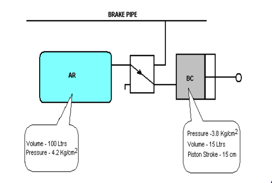
Whenever the brake pipe pressure is reduced below the CR pressure, the DV connects the auxiliary reservoir with the brake cylinder and the air from AR is sent into the brake cylinder to apply the brake. Whenever the brake pipe pressure is equal to CR pressure, the DV disconnects the BC from AR, and in turn connects the BC with Exhaust for the release of brakes fully.

Processes involved in working of Air brake system
- Charging
- Application
- Release.
- Manual Release
i) Charging of Air brake system
Brake pipe is charged with 5 Kg/Cm2 by the drivers brake valve from the Loco. Feed pipe is charged with 6 Kg/Cm2. AR is charged with 6 Kg/Cm2. (Up to 5 Kg/ Cm2 it is charged by both brake pipe and feed pipe. Beyond 5 Kg/Cm2 & up to 6 Kg/Cm2 it is exclusively charged by feed pipe.) The CR is charged through the distributor valve to 5 Kg/sq cm from BP. During charging Brake cylinder is connected to exhaust through distributor valve, to keep the brakes in released condition.

ii) Application of brake in Air brake system
For application the brake pipe is reduced in steps as given below.
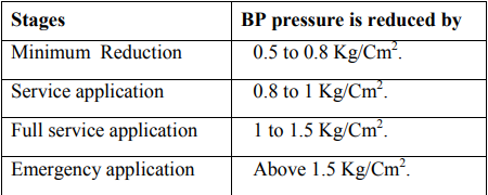
When the brake pipe pressure is reduced in steps as shown above, the air from AR is sent into BC to a maximum pressure of 3.8 Kg/ Cm2, during full service application as well as emergency application. During minimum reduction and service application the admission of air from AR in to BC is directly proportional to the reduction in the BP pressure.
Note: Before AR is connected to BC, the AR and CR are disconnected from BP, and BC also is disconnected from Exhaust. The AR is continuously charged to 6 Kg/Cm2 during brake application by Feed pipe. The CR pressure should remain at 5 Kg/Cm2. However there may be a little drop in CR pressure during brake application, due to the design.

iii) Releasing/Recharging of Air brake system
During release, the BP pressure is increased in steps. When the BP pressure is increased in steps, the brake cylinder is disconnected from AR and in turn connected to exhaust. The air from Brake cylinder is released / vented progressively depending upon the increase in the brake pipe pressure. When the brake pipe pressure is brought to 5 Kg/Cm2 the air from brake cylinder is completely exhausted and the brakes are released fully.

iv) Manual Releasing
Whenever the loco is detached, BP pressure is brought to zero and brake application takes place due to the existence of CR pressure at the bottom of the main diaphragm. To release the brakes manually, the hollow stem in the DV should be brought to the normal position by releasing the air from CR. To facilitate this, the release valve provided at the bottom of the DV is given a brief pull. During this operation, the air from CR is released which in turn brings the hollow stem to the normal position to connect BC with exhaust for releasing of brakes.
6.3.1 Requirement of choke for charging of Auxiliary reservoirs
With 100 ltrs capacity AR on each wagon, for a formation of 59+1 wagons approximately 6000 litres of air is required for charging the auxiliary reservoirs.
Main reservoir capacity of loco is only 750 litres, if the auxiliary reservoirs are charged directly without any restrictions; the main reservoir pressure will drop abruptly, which is not safe. In order to prevent the MR pressure from dropping abruptly, the air brake system is designed to use only the air delivered by the compressor (free air delivery) to charge the AR and to maintain MR pressure within prescribed limits. Hence auxiliary reservoirs are charged through restricted passage (choke).

6.3.2 Ensuring complete charging of the system
While charging the formation, Brake pipe is charged first before Auxiliary reservoirs. The volume of air required for charging the brake pipe for one wagon is only 10 litres. So a formation which consists of 58+1 wagons requires approximately 600 litres of air for charging the brake pipe when compared to 6000 litres in the case of auxiliary reservoirs. As the free air delivery of compressed air from the loco is about 1500 to 2000 litres per minute at normal speed, moreover only 600 litres of air only required for the brake pipe, it is charged to the required pressure within a minute (60 Seconds).

Even though gauge fitted with brake and the feed pipe in the brake van records a minimum of 4.8 Kg/Cm2 and 5.8 Kg/Cm2 respectively within a minute, AR and CR are yet to be charged to the required pressure, for which it takes about 180 to 240 seconds. Hence to ensure full charging of the system at least 4 minutes to be allowed, then only brake application will be effective.
Requirement of twin pipe system in coaching stock
- Charging time of Auxiliary reservoirs
As the free delivery of compressed air from the loco is 1500 litres to 2000 litres per minute at normal speed, to charge 6000 litres of air in the auxiliary reservoirs, it takes about 180 to 240 seconds.
- To charge AR by 5 Kg/Cm2 = 240 Seconds (Maximum)
- To charge AR by 1 Kg/Cm2 = 48 Seconds (Maximum)
Application time:
The application time is the time taken by the Distributor valve to admit a pressure of 3.6 Kg/Cm2 in to Brake cylinder from the Auxiliary reservoir during Full service application or Emergency application.
- The application time for the coaching stock is 3 to 5 Seconds.
- The application time for the Goods stock is 18 to 30 seconds. After the Full service or Emergency brake application the brake cylinder gets a maximum pressure of 3.8 Kg/Cm2 from Auxiliary reservoir.
Releasing time: The releasing time is the time taken by the Distributor valve to release the air from Brake cylinder from 3.8 Kg/Cm2 to 0.4 Kg/Cm2.
Note: The releasing time does not depend upon the piston displacement but it depends upon the BC pressure only.
- The releasing time for the coaching stock is 15 to 20 Seconds.
- The releasing time for the Goods stock is 45 to 60 seconds.
The difference in the application time and release time between the coaching and goods stock DVs is achieved by varying size of the choke in DV between the AR and BC for the application, and by varying size of the choke in DV between Brake cylinder and Exhaust for the release. Hence the DVs of coaching & 183 freight stocks are not interchangeable, since the application and release timings are different for coaching and freight stock.
During brake application, as the air from Auxiliary reservoir is sent in to brake cylinder, there is always a reduction in the AR pressure and it is likely to drop to 4.2 Kg/Cm2. hence during release, it must be ensured that before the air from brake cylinder is released completely, the AR should be recharged to 5 Kg/Cm2, so that the system can be kept ready for next brake application.
To charge AR from 4.2 to 5 Kg/Cm2 the DV takes approximately 36 Seconds, and to release the air from BC from a pressure of 3.8 Kg/Cm2 to O.4 Kg/Cm2 the DV takes 45 to 60 Seconds in the case of goods stock.

From the above facts, as it is possible to recharge the AR from 4.2 to 5 Kg/Cm2 within the release time of 45 to 60 seconds, a Single pipe system itself is sufficient for the Goods stock.
In the case of coaching stock, to release the air from BC from the pressure of 3.8 Kg/Cm2 to 0.4 Kg/Cm2 the DV takes 15 to 20 Seconds. And to re-charge AR from 4.2 to 5 Kg/Cm2 after application, DV takes approximately 36 Seconds.

From the above fact, it is clear that it is not possible through DV to recharge the AR from 4.2 to 5 Kg/Cm2 within the releasing time of 15 to 20 seconds for the Coaching stock.

Hence it has become necessary to introduce one more pipe called feed pipe to recharge the AR always to 6 Kg/Cm2, from the other end of the AR within the release time of 15 to 20 seconds and there by auxiliary reservoir pressure is maintained to optimum level for repeated brake applications.
6.3.3 Passenger emergency alarm system
Passenger emergency alarm system is provided between the main brake pipe and the alarm chain. When the alarm chain is pulled, the air pressure from the Brake pipe is vented out through the 8 mm choke provided in the Passenger emergency alarm valve. Due to the sudden drop of air pressure from the brake pipe in the system, the airflow indicator in the Locomotive deflects from its normal position and also gives hooting signal. By this the driver 186 comes to know about the drop in BP in the formation and he applies the brakes to stop the train.
The passenger emergency alarm system consists of two main parts.
- Passenger emergency alarm valve (PEAV)
- Passenger emergency alarm signal device (PEASD)
The passenger emergency alarm valve (PEAV) consists of a spring loaded hollow piston fitted with a check valve at the bottom. It has also got a control chamber at the bottom of the piston and a brake pipe chamber at the top of the piston. An 8 mm diameter exhaust port is provided at the bottom of the valve to release the air from main brake pipe. The brake pipe chamber available at the top of the piston is connected with the PEASD through branch pipes.
The PEASD consists of a pilot valve which can be operated by pulling the chain by the passenger. It is also provided with two numbers of exhaust ports to facilitate the removal of air from the top of the piston (Brake pipe chamber) by pulling the chain.
WORKING
During charging the brake pipe chamber and the control chamber of PEAV is charged with 5 Kg/Cm2, the control chamber is charged through the restricted passage. The air which is available at the brake pipe chamber at the top of the piston is also made available at the top of the pilot valve of PEASD. During charging 187 the spring loaded check valve closes the passage between main brake pipe and the exhaust of PEAV. (Ref. fig)

Resetting of PEASD
Unlike vacuum brake, where in turning the disc will automatically reset the valve, in air brake system in addition to the turning the disc, the key which is integral part of PEASD has to be turned by 90 degree clockwise.
In recent modification a wire rope is connected to the PEASD so that it can be reset from ground level eliminating the need to climb the coach for resetting the PEASD.
6.4 Trouble shooting faults in air brake system en-route
The major problems noticed in the air brake system are
BP punctured / Hose burst, FP punctured / Hose burst, AR pipeline punctured or damaged, Malfunctioning of DV, Malfunctioning of PEAS.
BP punctured / Hose burst
In case of single pipe system, if brake pipe is punctured the brakes get applied on the full formation. The affected wagon should be detached from the formation.
In case of twin pipe system, if the brake pipe is punctured, the brake pipe of the affected coach can be by passed without detaching the coach by connecting the FP of the affected coach with the BP of the adjacent coach. A specially made intermediate coupling made by welding the FP and BP palm ends together is available to establish these connections.
FP punctured / Hose burst
The train has to be run with single pipe system isolating the FP pipe from the first coach itself.
AR pipeline punctured or damaged
If the branch pipe between the FP and AR is punctured, the Isolating cock provided on the branch pipe of FP of the particular coach can be isolated and that particular coach will work on single pipe system. If the branch pipe between the common pipe bracket and AR is punctured, both the isolating cocks on the BP and FP branch and also the DV to be isolated and the particular coach will not have brake power, this has to be endorsed on the BPC.
Malfunctioning of DV.
DV to be isolated and ensure the brakes are released. It has to be endorsed in BPC.
Malfunctioning of PEAS.
In the case of leakage through PEAV, if the leakage is not arrested even after resetting the PEASD, isolate the cock provided between the BP pipe and the PEAV.
6.5 Single car testing
The different tests conducted with a Single car test rig;
1. Leakage in Feed pipe.
2. Leakage in Brake pipe.
3. Brake cylinder filling time.
4. Brake cylinder releasing time.
5. Sensitivity test.
6. Insensitivity test.
7. Emergency application test.
8. Piston Stroke.
9. Leakage in the Brake cylinder.
10. Graduated Application test.
11. Graduated release test.
12. Working of PEAS.
13. Working of GEV.
14. Manual release Test.
Procedure for conducting of Single Car Test Rig

1. LEAKAGE IN FP AND BP.
- Charge the system fully.
- Close the Cock No. 1 and 3.
- Observe the pressure drop in FP and BP for three minutes.
The leakage rate in the FP and BP should not be more than

2. BC FILLING TIME
- Charge the system fully
- Bring the A-9 valve to full service application position.
- Observe the BC pressure.
- The BC pressure should reach to 3.6 Kg/Cm2 within. 3 to 5 seconds for Coaching stock 18 to 30 seconds for Goods stock.

- Observe the maximum pressure. It should be 3.8 Kg/Cm2.
3. BC RELEASING TIME
- Bring the A-9 valve to release position.
- Observe the BC pressure.
- The BC should drop from 3.8 Kg/Cm2 to 0.4 Kg/Cm2 within 15 to 20 seconds for Coaching stock 45 to 60 seconds for Goods stock.

4. SENSITIVITY TEST
- Open the cock No.7 and Charge the system fully.
- Close the Cock No.2 and Open the cock No.4.
- Wait for 6 seconds and close the cock No.4. (This will reduce the BP pressure by 0.6 Kg/Cm2 in 6 sec automatically)
- Observe the Brake cylinder. The brake should be in applied condition.
5. INSENSITIVITY TEST
- Open the cock No.7 and Charge the system fully.
- Close the cock No.2 and Open the cock No.5.
- Wait for 60 seconds and close the cock No.5. (This will reduce the BP pressure 0.3 Kg/Cm2 in 60 seconds automatically)
- Observe the Brake cylinder. The brake should not be in applied condition.
- Observe the BP and CR pressure. Both should be at 4.7 Kg/Cm2
6. EMERGENCY APPLICATION TEST
- Close the cock No.7 and Charge the system fully.
- Close the cock No.2 and Open the cock No.6.
- Observe the Brake cylinder pressure. The maximum BC should be 3.8Kg/ Cm2.
7. PISTON STROKE
After the emergency or full service application measure the piston stroke. It should be within

8. LEAKAGE IN BC
- After the emergency brake application observe the leakage in the Brake cylinder.
- The leakage in the BC should not be more than 0.1 KG/Cm2 in 5 minutes.
9. GRADUATED APPLICATION TEST
- Charge the system fully.
- Reduce the BP pressure in steps through A-9 valve.
- Observe the BC pressure. The pressure should increase in steps.

10. GRADUATED RELEASE TEST
- Increase the BP pressure in steps through A -9 valve.
- Observe the BC pressure. The pressure should decrease in steps.

11. WORKING OF PEAS.
- Charge the system fully.
- Pull the alarm chain from inside the coach.
- Observe the BP pressure and BC.
- BP pressure should drop and brake should apply.
- Reset the PEASD.
- Observe the BP pressure and BC.
- BP pressure should reach to 5 KG/Cm2 and brake also should release.
12. WORKING OF GEV (Guard Emergency Valve)
- Charge the system fully.
- Operate the GEV handle.
- Observe the BP pressure and BC.
- BP pressure should drop and brake should apply.
- Bring back the GEV to normal position.
- Observe the BP pressure and BC.
- BP pressure should reach to 5 KG/Cm2 and brake also should release.
13. MANUAL RELEASE TEST.
- Disconnect the test rig from the rolling stock.
- Pull the release valve handle.
- Observe the CR pressure and BC.
- The CR pressure should drop to 0 KG/Cm2 and Brake should release without any jerks.
PROFORMA FOR SINGLE CAR TEST (ICF COACH)
Coach No. Type of DV and Sl.No:
BP Pressure: FP Pressure: Sl. No. Check Specified Actual
1. Leakage rate
a) Brake pipe 0.2 Kg/cm2 per minute (max.)
b) Feed pipe 0.2 Kg/cm2 per minute (max.)
6.6 BOGIE MOUNTED BRAKE SYSTEM
In order to overcome the problems faced due to the breakages and malfunctioning of SAB en-route, and also due to the frequent breakages and replacement of Cast Iron brake blocks, Bogie Mounted Brake System is introduced. In this system, the brake rigging in the under frame and SAB’s are eliminated by mounting the cylinders directly on the bogie frame itself. Since the brake force available is less, High friction ‘K’ type composite brake block is used to overcome the deficiency in brake power.
6.6.1 Special features of Bogie Mounted Brake System
- External slack adjusters are eliminated.
- High friction composite “K” type brake blocks are used, whose life is increased by 5 to 6 times than that of cast iron brake blocks.
- It has an in-built slack adjuster by which the effective length of the piston rod can be increased by 305mm automatically; whenever the piston stroke exceeds 32mm due to wear on the brake blocks and the wheel.
- Totally 4 Nos. of 8” size brake cylinders (2 per bogie) are used in place of two Nos. of 14” cylinders in standard body mounted air brake system.
- The cylinders are mounted between central longitudinal members connecting the bogie transom and the head-stock on either side. It is provided with less No. of brake fittings, therefore easy to maintain. Unusual noise emitted by the anti-vibration bracket in case of SAB, on run is completely eliminated.
- The forces acting on the levers and truss beams is only 40% when compared to under frame mounted system, therefore the wear on the brake gear components are less, and hence the frequent replacements of these components are minimised.
- As the forces acting on the Truss beam is only 1 tonne, when compared to 3.2 tonnes in the under frame stock, 13 tonnes capacity truss beams are sufficient.
6.6.2 Bogie Mounted Brake Cylinders:
The Bogie Mounted Brake Cylinders are provided with an in-built slack adjuster to maintain a constant brake block clearance automatically. It is a single acting slack adjuster by which the clearance between wheel and brake block can be decreased automatically by increasing the effective length of piston rod whenever the piston stroke exceeds 32mm due to wear on the brake block and the wheel. The adjustment takes place during return stroke.

200 If the clearance between wheel and the brake blocks is less due to any reason, it does not bring the required clearance automatically.
6.6.3 Main parts of Bogie Mounted Brake Cylinder
The main parts of the Bogie Mounted Brake Cylinders are:

1.Adjusting Screw with ratchet; 2.Adjusting tube; 3.Rocker arm; 4.Plunger pin; 5.Roller plate; 6.Pawl housing ring; 7.Pawl; 8.Piston; 9.Trunnion body; 10.Front Cover; 11.Piston return spring; 12.Cross head; 13.Latch; 14.Resetting plate; 15.Pawl spring; 16.Plunger spring
Adjusting screw and the spindle
- It increases the effective length of piston rod automatically, whenever the piston stroke increases 32 mm due wear on the wheel and the brake block.
- It facilitates to increase or decrease the effective length of piston rod manually, whenever brake blocks are changed or piston stroke is adjusted. Adjusting screw and Ratchet assembly
- The adjusting screw is with ratchet one end. The adjusting screw is provided with a double start thread with a pitch of 1/8” (3.15mm). The ratchet is provided with 18 numbers of teeth.
- When the adjusting screw completes one full rotation, it makes the adjusting tube to move forward by 2x1/8” = ¼” (6.33mm)
- If the ratchet is moved/turned by one tooth, the adjusting screw is turned by 3600 ÷ 18 = 200, which inturn moves the adjusting tube outward by ¼ x 1/18 = 1/72” (0.33mm).
- From the above, it is clear that, to move the adjusting tube forwards automatically by ¼” it requires 18 return strokes.
Rocker Arm
- The Rocker Arm is fitted with piston head by means of shackles and it moves along with the piston head.

- The roller end of the rocker arm slides over the roller plate, and on the other end of rocker arm rests on the pawl housing through the plunger pin.
- The function of rocker arm is to press the pawl housing ring downward during return stroke and it allows/permits the pawl housing ring to move upwards during forward stroke.
Roller Plate
- The Roller plate is fixed at an angle with the front cover by means of bolts. The function of Roller plate is to displace the pawl housing vertically when the rocker arm moves horizontally. (OR) it converts the linear displacement of rocker arm into vertical displacement of pawl housing.

- The rocker arm should be kept horizontal position facing to the gauge face of the wheel in BMBS due to the following reason;
- When the brake is applied the piston rod which is connected to the floating lever moves in a circular path with respect to lever’s fulcrum point. This horizontal position of rocker arm facilitates the piston to move linearly outward as well as vertical downward along with the floating lever during brake application.
- If the vertical displacement of the piston is prevented by keeping rocker arm facing upwards will result in brake binding due to the jamming of piston with the cylinder.
Pawl Housing Ring / Pawl
- The pawl-housing ring is pivoted with pivot pin of trunnion body at one end and the other end of the pawl housing ring moves/turn freely.

- A spring-loaded pawl is housed at the free end of the pawl housing. At the bottom of the pawl housing a spring loaded plunger/sleeve is kept between trunnion body and the pawl housing to move the pawl housing upwards/outwards during forwards stroke. At the top, a plunger pin is kept between the rocker arm and the pawl-housing ring to move the pawl ring downward/inward during return stroke.
- The function of pawl housing and the pawl is to turn the ratchet by one tooth whenever the piston stroke exceeds 32mm to increase the effective length of piston rod during return stroke automatically.
Working of in-built slack adjuster
- When the piston stroke is within 32mm, the spring-loaded pawl in the pawl housing moves between the two teeth of the ratchet and keeps the effective length of piston rod unaltered.
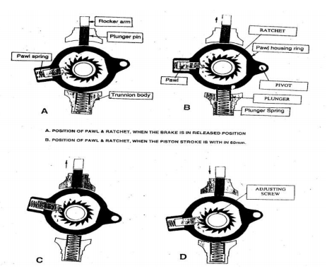
- When the piston stroke exceeds 32mm during the forward stroke due to the wear on the brake block and the wheel, the pawl slips and takes the position of next tooth in the ratchet.
- During the return stroke, the rocker arm pushes the plunger pin inwards/downwards which in turn turns the pawlhousing ring clockwise. The pawl which is housed in the pawl housing turns the ratchet with the adjusting screw by 200 causing the adjusting tube to move forward by 1/72” to increase the effective length of the piston rod.
Parts of Brake Rigging:
Lever- Straight, Lever – Z shaped, Lever Hanger, Connecting Link.

The schematic diagram of Brake rigging of BMBS is given below.

- Ensure the bogies are provided with the high friction composite “K” type brake blocks. Co-efficient of Composite K- type brake block is 0.28 - 0.3
- Ensure that the floating levers are not interchanged between AC and Non AC coaches.

- Ensure the levers are not reversed. Ensure the connecting links (pull rod) are not interchanged between AC and Non-AC coaches.

- Ensure the connecting link (pull rod) is not reversed. Whenever the wheel diameter is reduced to 839mm, ensure the brake gear connection is shifted to next inner hole of pull rod.

- Ensure 38mm packing is given between dashpot and the axle box wing whenever the wheel diameter is reduced to 839mm. whenever the red mark is seen on the adjusting tube; replace all the brake blocks since further take up of clearance is not possible.

- Ensure correct size of brake gear pins and bushes are used in brake rigging, and the piston stroke is within 32mm. If more, the in-built slack adjuster is defective, replace the brake cylinder.
- Ensure the rocker arm end is kept horizontal and facing towards the gauge face of the wheel.
Difference between under frame Mounted & Bogie Mounted brake system SN Description U/F Mounted brake System Bogie Mounted brake System


Procedure for replacing the Brake Blocks & adjusting the piston stroke:
Disengage the cross head from the adjusting tube, by pulling the latch. Turn the adjusting tube clockwise to decrease the length of adjusting tube (effective) length of piston rod. After replacing the brake blocks, apply the brake and check the piston strokes. If piston stroke is correct, engage the cross head with the resetting plate by releasing the latch. If the piston stroke is more, increase the length of adjusting tube, to decrease the clearance between wheel and brake block. If piston stroke is less, decrease the length of adjusting tube, to increase the clearance between wheel and brake block. After adjusting the piston stroke, ensure the cross head is locked with adjusting tube with the latch.
Maximum Stroke: ` This is the stroke beyond which the piston cannot come outward. It is 95mm for coaching stock.
Working stroke: This is the stroke at which, the in-built slack adjuster increases the effective length of the piston rod automatically whenever the clearance increases due to wear on the brake block and the wheel. It is 32mm for coaching stock.
The angle at which the roller plate is kept with horizontal position determines the working stroke. The roller plate should be kept at an angle of 10.50 with horizontal to have a working stroke of 32 mm for coaching stock.
Number of return strokes required to increase the effective length of piston rod automatically in BMBS
- 72 return strokes required for 1”
- 36 return strokes required for ½”
- 18 return strokes required for ¼”
Requirement of in built single acting slack adjuster in BMBC
The bogie mounted brake cylinders are designed to maintain a clearance of 6 to 8 mm between the wheel and brake block when the piston stroke is 25 to 32 mm. Generally the manual brake adjustment is done whenever the wheel diameter reduces and not if the thickness of brake block reduces. hence when a new brake block is fitted, before it could reach to condemning size it has to wear more than 35 mm, which in turn increases the clearance between the wheel and brake block gradually from 6 mm/8mm to 41/43mm. Piston stroke of up to 250 mm is required to have brake application in such case and it is not possible as the maximum piston stroke in BMBS is limited to 95 212 mm. hence inbuilt slack adjuster has become necessary to maintain a constant clearance between the wheel and brake block.
The inbuilt slack adjuster increases the effective length of piston rod automatically in order to maintain a constant clearance, whenever the piston stroke exceeds 32mm due to increased clearance on account of wear on the brake block and the wheel. The maximum pay out capacity of the piston rod is 305 mm.
6.7 DISTRIBUTOR VALVES
Functions of Distributor valves:
- It connects AR with BC during Brake application, connects BC with Exhaust during brake release.
- It charges AR to 5 Kg/Cm2 from BP during charging, disconnects the AR from BP during brake application, charges the CR to 5 Kg/Cm2 from BP during charging and disconnects the CR from BP during brake application.
- It admits a maximum pressure of 3.8 Kg/Cm2 during emergency as well as full service application. It admits the air from AR into BC in steps gradually, in proportion to the reduction in the Brake pipe pressure to facilitate graduated brake application and releases the air from BC in steps gradually, in proportion to the increase in the brake pipe pressure to facilitate graduated brake release.
- It reduces the BP pressure further by 0.4 Kg/Cm2 in addition to the brake pipe pressure reduced by the driver from the loco to accelerate the brake application particularly during minimum reduction. It admits air from AR into BC to a pressure of 0.8 Kg/Cm2 immediately 213 during brake application to overcome the resistance offered by the brake rigging.
- It applies the brake during sensitivity range, when the brake pipe pressure is reduced at the rate of 0.6 Kg/Cm2 in 6 seconds. It does not apply the brake during insensitivity range when the brake pipe pressure is reduced at the rate of 0.3 Kg/Cm2 in 60 seconds. It releases the air from CR, AR and BC during manual release. It isolates the brake system of the Rolling Stock whenever necessary.
Different types of distributor Valve, Their Manufacturers and present status

Mainly two types of DVs are used in Indian Railways
- EK type Distributor Valve & C3W Distributor Valve
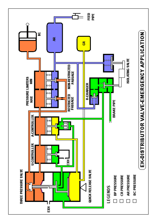
- EK Type Distributor Valve
The different sub-assemblies of EK type distributor valve are;
- Three pressure valve
- U-Controller
- Minimum pressure limiter
- Quick release valve A-Controller
- R- Charger
- Maximum pressure limiter
- Isolating valve

Three-pressure valve
Three pressures, i.e. BP, CR & BC pressure acts on this valve, It connects AR with BC during brake application. It connects BC with Exhaust during brake release. It admits BC pressure in steps, when the brake pipe pressure is reduced in steps, to facilitate graduated application. It releases air from BC in steps, when the brake pipe is pressure is increased in steps, to facilitate graduated release.
6.7.1 ‘LAP POSITION’ of distributor valve
This is the position of the Hollow stem of the Main Valve / Three pressure valve, in which the Brake cylinder is connected neither to AR nor to exhaust, during brake application / Release for the purpose of facilitating Graduated brake application / Release.
The hollow stem is designed to take LAP POSITION up to full service application in case of EK DV and even after Emergency application in case of C3W.
The Hollow stem takes LAP POSITION as soon as Brake cylinder gets sufficient pressure in proportion to the reduction in the BP pressure to facilitate graduated brake application and release, for this purpose in addition to the Main diaphragm one more diaphragm called BC diaphragm is connected with the hollow Stem.

During brake application, initially the hollow stem gets lifted, due to the difference of forces offered across the main diaphragm. The lifting hollow stem allows the air from AR into BC. As soon as BC gets sufficient pressure, which will offer a down ward force on the BC diaphragm equivalent to the upward force offered by the main diaphragm. Once the down ward force offered by the BC pressure on the BC diaphragm, equals the upward force offered by the main diaphragm, the hollow stem which is lifted initially, comes down to take LAP POSITION as shown in the figure.
U-Controller: The function of U-Controller is to reduce the Brake pipe pressure further by 0.4 Kg/Cm2, in addition to the brake pipe pressure reduced by the driver from the Loco, to accelerate the brake application.
Working: During brake application, particularly during minimum reduction, as soon as three pressure valve is lifted from its normal position, the BP chamber of three pressure valve is connected to exhaust through the U-Controller. The air from BP chamber of three pressure valve is exhausted immediately. This exhaust of BP pressure causes quicker reduction in BP pressure, which in turn helps to lift the three pressure valve quickly, to facilitate quicker application of brakes during minimum reduction
As soon as BC gets a pressure of 0.4 Kg/Cm2, the UController closes the passage between BP and exhaust, which in turn prevents any further drop in BP pressure.
A-Controller: It charges Control reservoir to 5 Kg/Cm2 from BP during charging and isolates the CR from BP, when the brake pipe pressure is reduced at the faster rate, during sensitivity range. It connects CR with BP, when the brake pipe pressure is reduced at the slower rate, during insensitivity range.
Note: This valve is normally kept in open position and synchronised with BC pressure. As soon as BC gets a pressure of 0.2 Kg/Cm2 A-controller closes the passage between CR and BP during the brake application. The additional check valve provided at the bottom of the AController closes the passage between CR and BP temporarily to prevent any loss in the CR pressure with the help of BP pressure, before it is permanently closed by the BC pressure.
Insensitivity range
It is likely that some leakage will crop up further in the train en-route, after the attention and dispatch. These small leakages should not lead to brake application, which can lead to detention to the trains. Hence a pressure drop of 0.3 Kg/Cm2 in 60 seconds is kept as insensitivity range for the DV not to actuate the brake application. Where as the pressure drop during sensitivity range is 0.6 Kg/Cm2 in 6 seconds. From the above it is very clear that the pressure drop during insensitivity range is 1/20th of pressure drop during sensitivity range. As the pressure drop is very less, the upward force offered by this pressure drop across main diaphragm also is less. This less force (1 Kg approximately at every second) is not at all sufficient to lift the hollow stem of the three-pressure valve. As the hollow stem is not lifted, AR is not connected to BC. We also know that there is a passage between CR and BP through A- Controller and this passage is closed as soon as BC gets a pressure of 0.2 Kg/Cm2 during brake application. Since the BC is not at all getting any air from AR, the passage between CR and BP remains in open condition and in turn allows the CR pressure also to release along with the brake pipe pressure at the rate of 0.3 Kg/Cm2 in 60 seconds.
As there is no pressure difference across main diaphragm at every point of time, the hollow stem is not lifted and thus brakes are also not applied during insensitivity range.

R-charger: R- Charger charges the auxiliary reservoir by allowing air from B.P. up to 5 kg/Cm2 in both single and twin pipe system during charging. It prevents back flow of air from AR to BP during brake application.
Minimum and Maximum pressure limiters: The function of Minimum pressure limiter is to admit a pressure of 0.8 Kg/Cm2 immediately in to the brake cylinder during brake application to overcome the resistance offered by the brake rigging.
The function of Maximum pressure limiter is to admit and limit to maximum pressure of 3.8 Kg/Cm2 into brake cylinder even after emergency application.
Working: Initially during brake application the air from AR is sent in to BC through two passages. One with restrictions and another without restrictions. As soon as BC gets a pressure of 0.8 Kg/Cm2 the minimum pressure limiter closes the non-restricted passage and further admission of air from AR to BC is through restricted passage. When the BC gets a pressure of 3.8 Kg/Cm2 the Maximum pressure limiter closes the non-restricted passage also. As both the passages are closed, the AR is completely disconnected from BC, and further admission of air from AR in to Brake cylinder is stopped.
Quick release valve: Quick release valve releases air from CR manually to facilitate manual release. The AR pressure can not be released by just pulling Quick release valve in case of EK make DV. For releasing AR pressure, DV handle has to be isolated.
Isolating valve:The functions of isolating valve are to isolate the DV in case of malfunctioning, release the air from AR manually, and release the air from BC manually.
Working: When the handle is in vertical (working) position the brake pipe is connected with DV. When the handle is in horizontal position, the Brake pipe is disconnected from DV. The AR and BC are connected to exhaust through the exhaust port provided in the isolating valve.
Note: Initially brake application will take place and after sometime the brake will release automatically, since BC is connected to Exhaust.
The sketch of EK type distributor valve with different subassemblies is given in the following pages. Path of air during charging, graduated and emergency application is shown in each page.


Different sub-assemblies of C3W type distributor valve are;
Main valve, Cut off valve, Quick service valve, In shot valve, AR check valve, Double release valve, Isolating valve.
Main valve: The functions of Main valve are;
- It connects AR with BC during brake application. It connects BC with Exhaust during brake release. It admits BC pressure in steps, when the brake pipe pressure is reduced in steps, to facilitate graduated application. It releases air from BC in steps, when the brake pipe is pressure is increased in steps, to facilitate graduated release. It also acts as a maximum pressure limiter, to admit a maximum pressure of 3.8 kg/Cm2 into BC during emergency brake application.
- Main valve is provided with two concentric pistons. One is larger and another one is smaller in area. During emergency brake application, leaving the larger piston in lifted position, the smaller piston along with hollow stem comes down to take LAP position as soon as BC gets maximum pressure of 3.8 kg/Cm2.
Cut off valve:
- It charges Control reservoir to 5 Kg/Cm2 from BP during charging. It isolates the CR from BP, when the brake pipe pressure is reduced at the faster rate, during sensitivity range. It connects CR with BP, when the brake pipe 225 pressure is reduced at the slower rate, during insensitivity range. It also charges AR to 5 kg/Cm2 during charging.
Note: This valve is normally kept in open position and synchronised with BC pressure. As soon as BC gets a pressure of 0.2 Kg/Cm2Cut off valve closes the passage between CR and BP during the brake application, which in turn prevents any further drop in CR pressure.
AR- Check valve:
The functions of AR- Check valve are;
- To charge the auxiliary reservoir from B.P. to 5 kg/Cm2 in single pipe system during charging through cut off valve. It prevents back flow of air from AR to BP during brake application.
Quick service valve:
- The function of Quick service valve is to reduce the Brake pipe pressure further by 0.4 Kg/Cm2, in addition to the brake pipe pressure reduced by the driver from the Loco, to accelerate the brake application.
Working:
During brake application, particularly during minimum reduction, as soon as the brake pipe pressure is reduced, the BP chamber of Main valve is connected to Quick service bulb through the Quick service valve. The air from BP chamber of Main valve is allowed to expand suddenly by sending the air into the Quick service bulb. This sudden exhasut of air from BP chamber of DV 226 causes the BP pressure to drop by 0.4 kg/Cm2, which in turn helps to lift the Main valve quickly, to facilitate quicker application of brakes during minimum reduction.
The air, which is sent into the Quick service bulb during brake application, is released through the exhaust port provided in the quick service valve during re charging.
Note: This valve is exactly opposite to that of Main valve.
In-shot Valve:
- The function of in-shot valve is to admit a pressure of 0.8 Kg/Cm2 immediately in to the brake cylinder during brake application to overcome the resistance offered by the brake rigging.
Working:
The In-shot valve is provided with two passages, one with restriction and another without restriction. Initially during brake application the air from AR is sent in to BC through both the passages. As soon as BC gets a pressure of 0.8 Kg/Cm2 the In-shot valve closes the non-restricted passage and further admission of air from AR is sent in to BC through restricted passage alone.
Double release valve:
- The function of Double release valve is to release the air from CR as well as from AR manually to facilitate manual release.
Working
This valve is provided with two check valves.
CR check valve & AR check valve
When the release valve is pulled only once (Short pull) the air from CR is released completely. On continuous release, the air from AR can also be released.

NOTE: The CR check valve is provided with a Locking rod arrangement, which enables the releasing of air from CR completely for a short pull. When the handle is pulled only once, the locking rod which is kept over the CR check valve drops in front of CR check valve, which in turn keeps the CR check valve in open position till the air from CR is released completely.
The AR check valve is not provided with the Locking rod arrangement, why because, it is not necessary to release the air from AR during manual release.
Isolating valve:
- Isolating valve helps to isolate the DV in case of malfunctioning. It releases the air from BP chamber of main valve on isolation.
Working:
When the handle is in vertical (working) position, the brake pipe is connected with DV. When the handle is in horizontal position, the Brake pipe is disconnected from DV and the BP chamber of main valve of DV is connected to exhaust. The BP pressure in the main valve is brought to zero immediately, and the brake application will take place due to the existence of CR pressure.
The different colour codes for the distributor valves are;
- For Coaches: Green
- For Wagons: Black.
6.8 BRAKE BINDING
It is the phenomenon of binding the wheels by the brake gear system or when brake block is in contact with wheel tread while the driver’s brake valve is kept in released position.
Implication of Brake Binding in the Railway System:
It has the direct bearing on the punctuality of trains. Nearly 30% cases of C&W punctuality losses were only on account of 229 “Brake Binding”. Besides punctuality loss, other consequences of brake binding on the Railway System are as under:-
- Damage to the wheels & sometimes coach detachments resulting revenue loss.
- Harassment to the passengers due to coach detachments resulting in their stranding in mid-section or change of coach.
- Poor Riding quality.
- Damage to the track.
- Damage to the Rolling Stock components such as Roller Bearings, springs etc.
- More tractive force needed to the locomotive.
- Unpleasant sound to the passengers.
Following are the factors causing “Brake Binding” in the coaches:-
C&W:
- Mal function of DV causing late release or leakage.
- Improper mounting of DV on common pipe bracket.
- Mal functioning of SAB.
- Isolating cock not working.
- Leakage in the brake system.
- Improper release of the rake while attaching/detaching/loco change by TXR staff at TXR stations. Defects in brake cylinder.
- Defects in dirt collector.
- Defects in brake gear.
LOCO & ITS OPERATION:
- Not giving proper release time after application.
- Variation of pressure/vacuum level during run/loco change.
- Malfunctioning of air flow meter resulting in non indication of ACP/leakage in brake system.
- Not stopping and resetting ACP/leakage after noticing air leakage through AFI.
- Inadequate pressure/vacuum creation/maintenance capacity of locomotive resulting in higher release time of the brakes.
- Driver misreporting brake binding to camouflage some other failure.
- Improper release of the rake while attaching/detaching/loco change by driver at non-TXR station.
OPERATING:
- Guard misreporting brake binding to camouflage some other failure.
- Improper release of the rake while attaching/detaching/loco change by guard at non-TXR station.
- Attachment of unexamined/untested stock after train maintenance and testing, especially VPU’s and other special stock.
- Not locking SLR guard cabin resulting in unauthorized persons traveling and tempering with Guard valve and hand brake.
LAW & ORDER:
- Frequent ACP operation.
- Operations of DV handle for brake application during run.
- Closing of angle cock in the coach ends.
- Operation of hand brake from SLR by unauthorized occupants.
MISCELLANEOUS:
- Hitting by ballast/foreign material resulting in breakage of dirt collector/ drain plug of AR/other brake system components.
- Cattle run over resulting in damage to brake system.
Following measures should be taken to contain brake binding incidences:-
Ensure proper maintenance of DV:
- Check holes of common pipe bracket are one-tomatched with the corresponding location on the Common Pipe Bracket (CPB) seal.
- Check collars provided on the CPB seals are uniformly projected.
- Use small quantity of hard grease on the CPB before positioning of the seal to avoid displacement while mounting.
- Check that release choke is clear.
- Overhaul/Repair distributor valve with intermediate flange as a single unit.
- Check holes of Intermediate flange seal are one-to-one matched with respective location in the distributor valve.
- Check collars provided on the seal are uniformly projected.
- Check the valve is free from rubber bulging or deboned for valve plate (10) in KE type or valve (37) in C, W type.
- Check for smooth movement of hollow stem in its guide during assembly. This may be ascertained by:
i) Movement of hollow stem. Check that hollow stem is not bent.
ii) Check that outer surface of the hollow stem is polished.
iii) Apply light coat of thin grease on the hollow stem.
Check the condition of CPB filter. This is asertained by:
i) Clean CPB filter in every schedule.
ii) Clean vertical passage in CPB.
- Identification of late releasing DV’s during maintenance.
- Locking of Distributor Valve isolating handle.
- In the POH phosphating and rewaxing of the Distributor Valve Body be done to avoid corrosion.
Proper inspection of dirt collector
- Clean Dirt collector in every schedule.
- Provision of Dirt Collector cover.
Proper inspection of brake regulator
- Identification of sluggish Slack Adjuster.
- Check that the barrel has no dent.
- Confirm that Traction sleeve passes smoothly inside the entire length barrel during assembly.
- Check axial play of the Adjuster nut with the spindle. Since actual measurement is difficult, excessive play must be felt while assembly.
- Make sure that the adjuster nut falls freely along the spindle when held vertical
Brake gear system
- Adjust end pull rod hole and maintain length of pull rod such that the Equalising levers be in near vertical in brake applied position.
- Ensure that the Z-lever pins used with Equalising levers are polished.
- Ensure the corresponding bushes are without any oblong deformation.
- Radial clearance is maintained within 0.75 mm.
- Ensure that the Actuating rod is not twisted. The straightness is realized by smooth fitment of the Actuating rod with the both Equalising levers with the pins.
Brake Cylinder
- Identification of sluggish brake cylinders during maintenance.
- Breathing passage clearing can be ascertained by avoiding greasing of Trunk during assembly and 234 cleaning annular space between Trunk and Front cover
Locomotive
- Check for fluctuation in BP pressure.
- Check for moisture/oil/dirt content in compressed air.
- Dynamic Brakes of the locomotive should be operative.
- Ensure proper working of air flow indicator and audio visual system.
- Locked axle of the locomotive is avoided.
Train Handling
- Wait for one minute at least after moving brake valve handle to release position after emergency application.
- Avoid extended application of the pressure surge to avoid over charging.
- Keep close watch in the air flow indicator to monitor incidence of excess leakage.
- Keep close watch in the Ampere meter reading for high current.
- Keep vigilant on tampering DV isolating handle position.
- Drain condensate from air reservoir, oil separator and filter.
- Open drain cock slowly so that condensate is carried out with the air.
Modification in coaches
- Brake Binding Indicator be provided on every coach.
- Hand Brake application indicator be provided on every SLR.
ACP system
- Oversize choke of the ACP be eliminated.
- Resetting key should be welded on the coach itself to properly reset the ACP.
- Proper releasing of coaches should be ensured after every ACP on the adjoining coaches also.
Training to the staff - C&W as well as operating & loco staff.
BP/FP pipes
- The Brake pipe & feed pipes should be secured with ‘T’ bolts to avoid decoupling en-route.
- Proper examination of feed pipe &brake pipes during maintenance.
System Improvement
- Introduction of Rolling out Examination to detect the coaches which are going in Brake binding condition. Also Rolling-In-Examination be ensured.
- Moisture separator/Air Dryer should be provided in all the locomotives & R.T.R pipe lines to avoid ingress of moisture in the air Brake system.
- Proper releasing of the rakes on the platform and on washing lines after maintenance.
- Pre-tested slack Adjuster and Distributor Valves should be replaced on the coaches,
- Coaches attached from the yard should be tested with the rake on W/Line.
Others
- Provisions of Quick Release pull rods.
- Pressure relief valve on the pipe line between Distributor Valve &the brake cylinder should be fitted so that the excessive pressure beyond 308 kg/cm2 is avoided.
- Pad locking of Guard cabin of the front SLR should be ensured by the Operating.
Trouble shooting & the remedial measures
1) Leakage rate of the much higher than the permitted value of 0.2 kg/cm2/min in BP line.


2) Leakage rate of the much higher than the permitted value of 0.2kg/cm2/min in FP line.


3) Both the Brake Cylinder Pistons of One Coach not coming out on Brake Application.

4) Brake Cylinder Piston Stroke of One or More Coaches is too less or in Excess.

5) Brake cylinder piston of one or more coaches not returning back on releasing brake.

6) Only one brake cylinder piston of a coach not returning back.

7) Alarm chain system on chain pulling showing no response of either hissing sound or partial brake application.

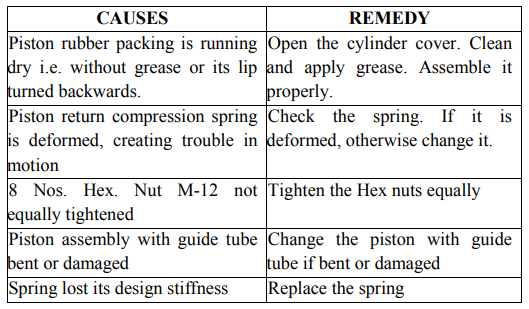
8) Brake cylinder air draining time is too long i.e., time taken is more than 20 seconds, piston is not returning to its original position

9) Alarm chain system is not working even after chain pulling i.e. no signs of brake application.


11) Regular hissing sound from PEAV is appearing during charging of the system or system is not charging appropriately.


12) No hissing sound from PEAV specially on pulling the pressure rod of PEASD and does not show any brake pressure reduction effect.


