
FREIGHT STOCK

Rolling stock used exclusively for transport of goods is termed as freight stock. Freight Stock are broadly classified either according to their under gear or according to utility.
Classification according to under gear:
i) Four wheeler wagon
ii) Bogie wagons
Four wheeler wagons:
At present only Brake van is in service, other 4 wheeler wagons like tank wagon and CRT wagons are phased out.
Bogie wagons:
There are four different types of bogies used in wagons. Diamond frame bogie, Cast steel Bogie, UIC fabricated bogie, CASNUB Bogie
Classification according to utility:
Open wagons, Covered wagons, Flat wagons, Hopper wagons, Well wagons, Container wagons, Tank wagons, Brake vans
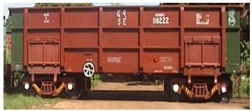
Open wagons:
These are wagons are used for transportation of coal, ore, limestone’s etc. which does not require protection from rain. The wagons are provided with flap doors for ease of loading/unloading of consignment.
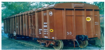
Covered wagons:
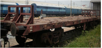
The consignments which required to be protected from rain etc; are transported in covered wagons. These wagons generally carry food grains, cement, fertilizers, fruits & vegetables etc. Flat wagons: These wagons are without side walls and are generally used for carrying steel coils, billets, rails sleepers etc.
Hopper wagons:
These are special wagons designed for Rapid discharge from bottom. These are used for transporting coal and ballast.
Well wagons:
These wagons have well shaped under frame and are used for larger consignments like military tanks, heavy equipments etc.
Container wagons:
These are special flat wagons designed for handling containers.
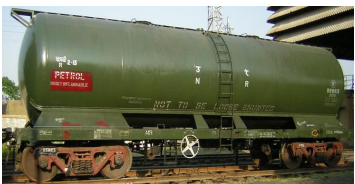
Tank wagons:
These are wagons designed to carry liquid consignment like petroleum products, milk, edible oils, etc.
Brake vans:
These are guards van used with freight trains as last vehicle.
9.1 OPEN WAGONS
i. BOY: Designed in 1967 for heavy minerals. Axle Load - 22.9t. Cast Steel Bogie. It has no doors. Speed 65/75 Kmph.

ii. BOY EL: Introduced in 2006 for operation at 25t Axle Load. Bogie -Casnub 22NLC. Differentiated from BOY by an Olive Green Band. Speed restricted to 50/65 Kmph.
iii. BOXN: Designed in 1980 for coal. Axle Load - 20.32t. CASNUB Bogie, Speed 75/80 Kmph.

iv. BOXN M1: In 2005 for increasing the CC up to CC+8+2t, suspension of BOXN is augmented by providing additional springs. A caption “Fitted with additional springs for Axle Load of 22.2t” in the centre of the wagon in golden yellow is printed to differentiate. Bogie side frame is also painted with Golden Yellow band. Speed 70/80 Kmph for CC+6+2t & 60/80 Kmph for CC+8+2t.
v. BOXN EL: Introduced in 2006 for operation with 25t Axle Load. Bogie - Casnub22 NLC. Differentiated from BOXN by an Olive Green Band. Speed restricted to 50/65 Kmph.
vi. BOXN HS: Designed in 2000. Variant of BOXN with Casnub 22HS bogie for increasing speed. Differentiated from BOXN by a Golden Yellow band. Speed 100/100 Kmph.

vii. BOXN HSM1: In 2005 for operation up to CC+8+2 t, suspension of BOXNHS modified by providing two additional inner springs. Differentiated from BOXNHS by a caption “Fitted with additional springs for Axle Load 22.82t” in centre of the Golden Yellow band. Bogie side frame also provided with Golden Yellow band. Speed 75/90 Kmph for CC+6+2t and 60/90 Kmph for CC+8+2t.
viii. BOXN CR: Designed in 1999. Material of body of BOXN changed to stainless steel (IRS: M 44). Other parameters are same as BOXN.
ix. BOXN R: Designed in 2007. It is upgraded rehabilitated version of BOXN. Entire superstructure of MS replaced with Stainless steel (IRS: M 44). Height is 177 mm more than BOXN. Carrying capacity increased by 6t. Nine 295 stanchions provided, instead of 6 in BOXN. Axle Load - 22.9t.

x. BOXNHA: This wagon was designed in 2001 for transportation of coal with an axle load of 22.1t. Bogie - IRF 108HS. Its height is more than BOXN. Speed at 20.32t and 22.1t Axle Load 100/100 Kmph and at 22.82t Axle Load 60/65 Kmph. xi. BOXN LW: Designed in 1988 to meet the requirement of higher pay to tare ratio. Axle Load - 20.32t. Casnub22HS bogie, Width is 50 mm more than BOXN. Stainless steel (IRS: M44) & corton steel (IRS: M41) used in body and under frame and Cold Rolled Formed (CRF) sections were used in design to reduce the tare weight of the wagons. Manufacturing of this wagon started in 2005. Speed 100/100 Kmph.
xii. BOXN LWM1: In year 2008, design and Suspension of BOXNLW modified for operation up to CC+8+2t. Speed 60/65Kmph for both CC+6+2t and CC+8+2t. 296
xiii. BOXN HL: Designed in year 2005, 250mm longer, 76mm higher & 50mm wider than BOXN. Axle Load - 22.9t. Casunub22HS Bogie. Stainless steel (IRS:M44) and CRF section used in body and under frame to reduce tare weight (20.6t). Has been provided with improved quality coupler and draft gears. PU painting is used. Initially red oxide colour specified, later on changed to phirozi blue. In red oxide colour wagons ‘SS’ written on side in a circle in phirozi blue colour for identification. Speed 75/100 Kmph.

xiv. BOST: Designed in 2000 for long steel products. Axle Load - 20.32t. CASNUB 22HS Bogie. Speed 75/80 Kmph.
xv. BOST M1: In 2006 for operation up to CC+6+2t, it is modified by providing additional springs. Differentiated from BOST by a caption “Fitted with additional springs for Axle Load 22.32t” in centre of the wagon in Golden Yellow. Speed 60/65 Kmph.

xvi. BOST HS: Designed in 2004. Variant of BOST with Casnub 22HS (Mod-1) bogie for increased speed. It is differentiated from BOST by a Golden Yellow Band. Speed 100/100 Kmph. xvii. BOST HS M1: In 2007 for operation up to CC+6+2t. it is differentiated from BOSTHS by a caption “Fitted with additional spring for Axle Load 22.32t” in centre of the Golden Yellow Band. Speed 60/80 Kmph. xviii. BOST HS M 2: Designed in 2006 for increasing speed. Axle load 22.32t. Variant of BOSTHS with CASNUB 22HS (Mod-II). Speed 60/100 298
9.2 COVERED WAGONS
i. BCN: Designed in 1984 for transportation of bagged commodities. Axle Load 20.32t. present stock is mostly with CASNUB 22NLB, Speed 75/80 Kmph.

ii. BCN M 1: Introduced in 2006 for operation up to CC+8+2t. It is differentiated from BCN by a caption “Fitted with additional springs for Axle Load 22.82t” in centre of the wagon in Golden yellow. Golden Yellow Band is provided on bogie side frame also. Speed 75/80 Kmph for CC+6+2t and 65/80 Kmph for CC+8+2t.
iii. BCN A: Designed in 1990 by reducing the length of BCN wagon and increasing height, there by increasing the number of wagons in a rake to 44. Axle Load 20.32t. Bogie is CASNUB 22NLB, Speed 80/80 Kmph.
iv. BCNA M 1: Introduced in 2006 for operation up to CC+8+2t. It is differentiated from BCNA by a caption “Fitted with additional springs for Axle Load 22.82 t” in centre of the wagon in Golden yellow. Golden Yellow Band is provided on bogie side frame also. Speed 75/80 Kmph for CC+6+2t and 65/80 Kmph for CC+8+2t.
v. BCNA HS: Designed in 2001, variant of BCNA with CASNUB 22HS bogie for increased speed. It is differentiated from BCNA by a Golden yellow band. Speed 100/100 Kmph.
vi. BCNA HSM 1: Introduced in 2006 for operation up to CC+8+2t. It is differentiated from BCNAHS by a caption “Fitted with additional springs for Axle Load 22.82t” in centre of the wagon in Golden yellow. Golden Yellow Band is provided on bogie side frame also. Speed 75/100 Kmph for CC+6+2t and 65/100 Kmph for CC+8+2t.
vii. BCN HL: Designed in2006 for bagged commodities. Axle Load 22.9t. Length is further reduced and both width 300 and height increased compared to BCNA. Hence number of wagons per rake increased to 58. Bogie is of CASNUB 22 HS type. Stainless steel (IRSM: M44) and CRF sections used in body and under frame construction to reduce the tare weight. Has been provided with improved quality coupler and draft gears. PU painting of Phiroziblue colour is used. Speed 65/65 Kmph.

viii. BCCN/BCCN A/BCCN B: BCN variants for carrying bulk cement (not packed in bags). Loading is through ports at the top; unloading via chutes at the bottom.

ix. NMG: These are not narrow-gauge wagons, despite the classification code. The class code 'NMG' stands for 'New Modified Goods'. These are single-decker automobile carriers constructed out of old ICF and BEML passenger coaches. The design is not entirely uniform but generally all the windows and doors on the side walls are removed and the opening closed. End body is modified by providing doors to allow vehicles to be driven into it.

9.3 FLAT WAGONS
i. BRN: Designed in 1992 for transportation of rails and heavy steel products. Axle Load 20.32t. provided with CASNUB 22 NLB, Speed 75/80 Kmph.

ii. BRN A: Designed in 1994, improved version of BRN. The design is riveted cum welded construction. Higher pay to tare ratio, compared to BRN. Other parameters are same as BRN. Speed 75/80 Kmph. iii. BRN AHS: Designed in 2001. Variant of BRNA with CASNUB22HS bogies for increased speed. Speed 100/100 Kmph.
iv. BFNS: Designed in 2002 especially for transportation of hot rolled/cold rolled coils, plates, sheets and billets etc. This is the first wagon designed in Indian Railways to carry point load. Provided with CASNUB 22HS bogie, Axle Load 20.32t. Speed 100/100 Kmph.

v. BRHNEHS: This bogie rail wagon was designed in 2004 for use of Engineering department of various Zonal Railways for Track Relaying Train (TRT), specially for loading RCC sleepers. Axle Load 20.32t. provided with CASNUB 22HS Bogies. The design was provided with Transition CBC and air brake system. Speed 50/65 Kmph.
9.4 HOPPER WAGONS
i. BOBSN: Designed in 1994 for transportation of iron ore, Axle Load 22.9t. Provided with modified CASNUB 22NLB bogie. It is provided with side discharge. Speed 75/75 Kmph.

ii. BOBSNM1: In 2006 for operation at A/L 25t, suspension of BOBSN modified by providing 4 additional inner springs, Bogie renamed as Casnub22NLC. Speed 50/60.
iii. BOBR: Designed in 1986 for transportation of Coal, it is provided with bottom discharge. Axle Load 20.32t. Provided with CASNUB 22NLB bogie, Speed 80/80 Kmph.

iv. BOBRM1: Introduced in 2006 for operation up to CC+6+2t. It is differentiated form BOBR by caption “Fitted with additional springs for A/L 22.32t” in centre of wagon in Golden Yellow. Golden Yellow Band is provided on bogie side frame also. Speed 70/75 Kmph.
v. BOBRN: Designed in year 1991 by reducing the length of BOBR wagon to increase the number of wagons in a rake to 58 (from 53 of BOBR). Axle Load 20.32t. provided with CASNUB NLB bogie. Speed75/70 Kmph.
vi. BOBRNM1: Introduced in 2006 for operation up to CC+6+2t, it is differentiated from BOBRN by a caption “Fitted with additional springs for A/L 22.32t” in centre of wagon in Golden Yellow. Golden Yellow Band is provided on bogie side frame also. Speed 70/80 Kmph.
vii. BOBRNHSM1: Designed in 2006 for Axle load of 22.32t. Variant of BOBRN with modified CASNUB 22HS Bogie for increased speed. Instead of BOBRNHS this (BOBRNHSM1) was manufactured. Speed 60/100 Kmph.
viii. BOBRNEL: Introduced in 2008 for operation at Axle Load of 25t. It is differentiated from BOBRN by an olive Green band. Speed restricted to 50/65 Kmph.
ix. BOBYN: Designed in year 1996 for transportation of ballast for engineering department. It has chutes at side & bottom for discharging ballast on both sides and centre of rails. Provided with CASNUB 22NLB Bogie, Axle Load 20.32t. Speed 75/75 Kmph.

x. BCBFG: Bogie covered Hopper Wagon for Food Grain. This wagon has been designed for transportation of food grain in bulk. It is provided with CASNUB-22HS Mod-I bogie, Non transition CBC, single pipe graduated release air brake system with automatic load sensing device. There are 2 Nos. gravity discharge gates at bottom for unloading. Axle Load 21.82t, speed 65/65 Kmph.

9.5 TANK WAGON
i. BTPN: Bogie Tank Wagon. This wagon was designed in 1986 for transportation of petroleum products i.e. Kerosene, petrol, diesel and naphtha. Axle Load 20.32t. CASNUB 22 NLB bogie. Speed 80/80 Kmph.
ii. BTFLN: Improved version of BTPN, designed to increase the pay load. This tank is without complete under frame; hence the tare weight is reduced from 27t to 23.53t. Pay load is increased from 54.28t to 57.75t increasing the pay/tare ratio from 2.0 to 2.45. the volume is also increased from 70.4 m3 to 76 m3. since the under frame is not available the brake system is also modified to Bogie mounted brake system, with rigging components only on bogies.

iii. BTPGLN: This wagon is designed for transportation of LPG. Provided with Air brake and CASNUB 22NLB bogie, Axle Load is 20.32t. Speed 75/80 Kmph.

iv. BTALN: Bogie Ammonia Tank Wagon. This tank wagon was designed in 1984 for transportation of anhydrous liquid ammonia. Provided with UIC Bogie, Axle Load is 20.32t. Speed 65/65 Kmph.
v. BTCS: Bogie Caustic Soda Tank Wagon. This wagon was designed in 1980 for transportation of Caustic soda. Bogie CASNUB 22W. Axle Load 20.32t. Speed 65/65 Kmph.

vi. BTAP (Bogie Alumina Tank Wagon): This wagon was designed in 1982 for transportation of Alumina powder. It is gravity loaded and has provision of fluidizing for evacuation. Present stock is fitted with CASNUB 22NLB bogie, Single pipe Air Brake System & non transition high tensile CBC. Axle Load 20.32t. Speed 65/65 Kmph.

9.6 BRAKE VAN
i. BVZI: Bogie Brake Van
This 8-wheeled brake van was designed in 2004 with ICF bogie to achieve comfort level(Ride Index) equivalent to loco for goods guard and capable of running at 100 Kmph. The brake van is 5 meter longer than BVZC brake van.

ii. BVZC: 4 Wheeler Brake Van with Air Brake
This 4-wheeled brake van is fitted with 9 plated laminated bearing springs. Wheel base of 5400 mm. Fitted with cylindrical roller bearing wheels. Auxiliary reservoir capacity is 75 ltrs. Brake cylinder dia 304mm/12 inches. Speed potential 100 kmph.
9.7 CONTAINER WAGONS
i. BFKN: Bogie Container Flat Wagon. Broad gauge Bogie Container flat wagon type BFKN is modified version of BFKI wagons, which are in operation on IR from 1975 for transportation of containers (max pay load of 48t). Operating speed is 75 kmph. Modified BFKN (Air brake & enhanced pay load) wagons can carry payload of 61t. these wagons are fitted with indigenous designed Retractable Anchorage Locks (patented) to secure containers.

ii. BLCA/BLCB: Bogie Low Platform Container Flat Wagon. Designed in 1994 for transportation of 20’ & 40’ long ISO containers with operation speed of 100 kmph. Lower height of under frame floor from R/L. has been achieved with introduction of hybrid design of bogie frame, bolster and use of smaller diameter wheel in LCCF 20(C) bogie, Axle Load 20.32t. Speed 100/100 Kmph. Provided with Automatic twist lock for securing of containers on the wagon.

iii. BLLA/BLLB: Bogie Low Platform Longer Container Flat Wagon. Designed jointly by RDSO & RITES in 2001 for transportation of 22’, 24’ & 45’ containers. There is provision for carrying 20’ & 40’ long ISO containers also. Except the under frame the bogies are all of BLC wagons. Axle Load is 20.32t. Speed 100/100 Kmph.
DOUBLE STACK CONTAINER OPERATION:
In March 2006 double stack container train operation started with restricted speed of 75kmph. This was for the first time in the world that double stack container train operation of flat wagon was done. Speed 75/75 Kmph.
i. BLCAM/BLCBM: In the year 2007 bogie of BLC wagon was modified by providing upgraded side bearer, upgraded friction wedge & 2 additional inner springs for double stack container operation with Axle Load of 22t & 100kmph speed.
ii. BCACM: In the year 2007, to meet the immediate requirement of auto car industry, design of existing container flat wagons (A type & B type) modified by provision of a suitable bi-level structure for transportation of auto cars. One rake can carry up to 270 auto cars. Two such rakes converted by Jagadhari Workshops are in operation.

9.8 BOXN WAGON
SAILENT FEATURES OF BOXN WAGON


9.8.1 DETAILED SAILENT FEATURES OF BOXN WAGON:-
1. No. of doors in BOXN wagon- 2 (on one side, at both ends)
2. DRAW & BUFFING GEAR:-
- High capacity, high friction draft gear used
- High tensile straight CBC used.
- CBC coupler working capacity – 120 ton.
- Proof load – 170 ton.
- Hauling capacity in 1:10. In up gradient – 9000 ton.
3. BOGIE:-
- CASNUB bogie used.
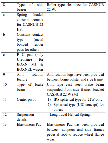
- Axle load capacity 22.9 ton.
- Secondary suspension, helical spring used.
- Side frames are joined through spring plank & bolster.
- UIC spherical type centre pivot fitted [except 22 W, 22 W(R)].
- Metal bonded constant contact rubber pad side bearer used.
- Fit for 90 kmph, 100 kmph for HS.
- Maintenance cost is less.
- Head stock with diagonal bar is removed.
4. BRAKE GEAR:-
- Single pipe air brake system.
- SAB, empty load device used.
- Clearance between wheel & brake block is maintained through SAB. 317
- Pocket liner type brake beam.
- No. of brake beam – 4.
- No. of brake block – 8.
5. RUNNING GEAR:-
- Axle load – 22.9 ton.
- CTRB used.
- New wheel dia. – 1000 mm.
- Condemning dia. – 906 mm.
- Journal centre – 2260 mm.
- Dia. Of journal – 144.5 mm.
6. OTHER FEATURES:-
- Ratio of pay load to tare weight – 2.72
- Track loading density (gross) – 7.59 ton/m
- Volumetric capacity-56.29 cu meter
- Overall width- 3200 mm
- Length over center buffer face – 10713 mm
- Bogie center – 6524 mm
- Wheel base- 2000+/- 5 mm
- Height of CBC from rail level -1105 mm
- Distance between side bearers -1474 mm
- ‘A’ dimensions-70+2/-0 mm
BOGIE STOCKWAGON
I) Diamond frame bogie - Used in BOB wagons
II) Cast steel bogie – Used in BWT wagons
III) UIC fabricated bogie – Used in VAC. Brake Bogie Stock
IV) CASNUB Bogie – Used in Air Brake Bogie Stock


COMPARATIVE STUDY BETWEEN UIC AND CASNUB BOGIES SN UIC BOGIE CASNUB BOGIE


9.9 CASNUB BOGIE
CASNUB BOGIE means Cast Steel Bogie equipped with snubber spring . Bogie comprises of two cast steel side frames and a floating bolster. The bolster is supported on the side frame through two nests of spring, which also incorporate a load proportional friction damping .the side frames are connected by a fabricated mild steel spring plank to maintain the square ness of the bogie.

History:
- The CASNUB bogie was first tested in 1972 under BOI wagon and was found safe to run at test speed up to 110 kmph.The test result have been published in RDSO’s mechanical engineering report no. M -265. 323
- In 1981 trials were again undertaken on these bogies under BOXN wagon to maintain the main line standard and its behaviour was well within safety limits up to 90 kmph speed and was designated as CASNUB 22W . These were modified as CASNUB 22W(M) mainly to take care of high wheel wear reported on earlier versions . Subsequently CANUUB 22 NL (Narrow jaw) and CASNUB 22 NLB (Narrow jaw with fish belly bolster) version were introduced.
- CASNUB 22 HS bogies have been developed for high speed operation with maximum permitted speed up to 100kmph.
SALIENT FEATURES OF CASNUB BOGIE: SN ITEMS DESCREPTION

BOGIE COMPONENTS
Version of CASNUB Bogie:
CASNUB 22 W (MARK I)
CASNUB 22W RETROFITTED
CASNUB 22 NL
CASNUB 22 NLB
CASNUB 22 HS
BOXN, BCN, BCNA, BRN, BTPN, BTPGLN, BOBR, BOBRN, BOBY, BOBYN, BFK
Detail of Load and Snubber Spring Arrangement


CASNUB 22 (W) R Bogie: In 1990 CASNUB 22 (W) Bogies were provided with 46mm thick EM pad between pedestal crown and adopter to reduce the developing of false flange in wheel sets, for that the following modification were adopted in
CASNUB 22 (W) Bogie.
1) Used of 46mm thick EM pad
2) Reduction in Height of adopter by 29.5mm
3) Used of New Wheel in dia. of 956mm
4) Position of retainer bolt is kept below by 32mm
5) Position of S.F.KEY is reversed on its location.
6) Provision of floating bolster
7) IRS pivot riveted and welded or casted
8) Constant contact metal bonded rubber pad in side bearer
9) Sliding packet type brake beam
10) Weight 5.35 T 331
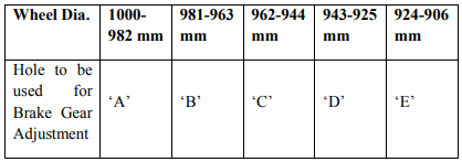
CBC HEIGHT ADJUSTMENT IN CASNUB BOGIE FITTED STOCK:
As per Wheel Dia. WEAR 12 mm. and 37 mm. thick metal packing are utilized as under:-
Use of 12 mm. thick packing

Use of 37 mm. thick packing

Note: 37 mm thick Packing is not utilized in Casnub 22 W (R) Bogie.
Adjustment of Brake Gear Pin in Bogie
ROH of BOXN wagon
ROH of BOXN wagon is carried out at selected major sick line where all ROH facilities for BOXN wagon is available at a definite interval.
The First POH of BOXN wagon is carried out at a interval of 6 years/(72 months) &subsequent POH periodicity is reduced to 4 ½ years/(54 months) accordingly railway board/RDSO has decided to carry out 3 ROH after a interval of 18 months before first POH & 2 no. of ROH in between subsequent POH.
The complete wagon has been broken down into 5 major sub systems:
1) The body including under frame, super structure & brake rigging.
2) CASNUB bogie.
3) Air brake system.
4) Center buffer coupler
5) Wheel, axle and bearing.
Each sub system is further split into individual items and the particular work to be done in respect of each item is indicated under the different ROH schedules.
BODY
1. UNDER FRAME :-
2. SIDE WALL :-
3. UNDER GEAR:
CASNUB BOGIE
1. BOLSTER:-
2. SIDE FRAME
3. WEDGE:
4. CENTRE PIVOT (BOTTOM)
5. COIL SPRING:
6. BOGIE BRAKE GEAR:
AIR BRAKE SYSTEM
1. DISTRIBUTER VALVE:
2. BRAKE CYLINDER:
3. CUT OFF ANGLE COCK:
4. DIRT COLLECTOR:
5. RESERVOIR:
6. HOSE COUPLING:
7. METAL PIPES AND JOINTS:
8. SLACK ADJUSTER:
9. AIR BRAKE SYSTEM:
CENTRE BUFFER COUPLER
1. CBC BODY:
2. KNUCKLE:
NOSE: Replace if wear more than 4.3mm with H.T.E. knuckle. Knuckle with nose wear more than 4.3mm and less than 9.0mm can be used in yard replacement.
3. STRIKER CASTING:
4. COUPLER MECHANISM:
5. DRAFT GEAR:
6. GENERAL:
WHEEL, AXLE AND BEARING
1. AXLE:
2. WHEEL:
3. BEARINGS:
4. ADAPTER:
CROWN SURFACE: Replace if worn to relief depth.
SIDE LUG: Replace/reverse and use.
THRUST SHOULDER: Replace if depth exceeds 0.7mm.
MACHINED RELIEF: Replace if depth exceeds 0.8mm.
SUMMARY ROH of AIR BRAKE WAGON WITH CASNUB BOGIE:-
BOXN wagons are to be given Routine Over-Haul (ROH) normally after every 18 month at the nominated sick line/wagon depot, where proper facilities are provided. The ROH schedule is as follows:
a) Lift the body, keep it on trestles & run out bogies.
b) Strip bogie component for examination & repair as below:-
c) Strip brake gear levers & rods for examination of worn outs/ damaged parts.
d) The equipment shell be given attention in accordance with the maintenance manual issued by respective air brake equipment manufacturer:-
i. Cleaning of strainer discs.
ii. Lubrication of brake cylinders/ cleaning of its strainer.
iii. Check for easy operation of isolating cocks & anti pilferage device of distributor valve cut off angle cock, manual quick release valve & isolating cock.
iv. Draining of auxiliary reservoir.
v. Checking of hose coupling for serviceability.
vi. Cleaning of a strainer.
vii. Dirt collector to be cleaned.
viii. Leakage in pipe & joints to be checked.
ix. After carrying out above items of work the wagon shall be tested for proper function of air brake system with single car test device in accordance with the procedure indicated below:-
e) Clean horizontal levers, hand brakes & gears & lubricate.
f) Examine head stock for damage, bend / cracks.
g) Refit brake gears levers & rods, Lubricate pins & other equipment & apply graphite to horizontal levers of empty load box.
h) Replace worn out brake blocks. Check wheel profile, turn the wheel as needed. UST of axle to be carried out & turning of wheel to worn wheel profile during ROH.
i) All the wheels are to be checked ultrasonically & axle box cap bolts are to be tightened up by torque wrench with proper torque & in no case old locking plates are to be reused.
j) CBC knuckles are to be checked by contour gauge, anti creep / articulated rotary operation of locking arrangement to be checked.
k) Manual adjustment of brake gear to be done in accordance with wheel diameter. Modification works are to be attended as issued by RDSO from time to time.
9.10 BLC WAGONS
Bogie Low platform flat wagons for carrying ISO containers.

Different sizes of containers:

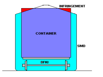
BFKI wagons, the overall dimensions exceeds the Standard moving dimensions of X – class engine by 254 mm at the top side. And the load is to be moved as ODC with speed restrictions. This in turn affects the speedy movement of containers.


- Side frame with friction plates
- Spring plank
- Bolster with wear liners
- Friction Shoes
- Load bearing spring
- Center pivot top & bottom
- Bolster pivot pin
- Side bearer
- Wheel sets with bearing units
- Side frame key with Key bolt, nut, spring washer &split pin.
- Elastomeric pads.
- Bogie brake gear components.
- Packing piece of CBC height adjustment
Version of CASNUB Bogie:
CASNUB 22 W (MARK I)
- Introduced in 1972
- Weight 5.35 T
- Provision of adapter retainer bolt in outer jaw
- E M pad not provided
- Provision of wide jaw adapter
- Provision of floating bolster
- IRS pivot riveted and welded or casted
- Clearance roller type side bearer
- Sliding packet type brake beam 326
- Fitted with CTRB
CASNUB 22W RETROFITTED
- Introduced in 1990
- Weight 5.35 T
- Provision of adapter retainer bolt in outer jaw
- E M pad provided
- Provision of wide jaw adapter with 25.5 mm thickness
- Provision of floating bolster
- IRS pivot riveted and welded or casted
- Constant contact metal bonded rubber pad in side bearer
- Sliding packet type brake beam
- Fitted with CTRB
CASNUB 22 NL
- Introduced in 1989-90
- Weight 5.5 T
- Narrow jaw adapter provided
- Adapter retainer bolt not provided
- E M pad provided
- Provision of floating bolster
- IRS pivot riveted and welded
- Constant contact metal bonded rubber pad in side bearer
- Sliding packet type brake beam
- Fitted with CTRB
CASNUB 22 NLB
- Introduced in 1990-91
- Weight 5.4 T
- Narrow jaw adapter provided
- Adapter retainer bolt not provided
- E M pad provided
- Fish belly shaped bolster
- Weight reduced
- Spherical type centre pivot
- Constant contact type mental bonded rubber pads in side bearer
- Sliding pocket type bake beam
- Fitted with CTRB
CASNUB 22 HS
- Introduced in 1993
- Weight 5.4 T
- Narrow jaw adapter provided
- Adapter retainer bolt not provided
- E M pad provided
- Spherical type centre pivot
- Spring loaded side bearer
- Sliding pocket type bake beam
- Fitted with CTRB These bogies are used in
BOXN, BCN, BCNA, BRN, BTPN, BTPGLN, BOBR, BOBRN, BOBY, BOBYN, BFK
Detail of Load and Snubber Spring Arrangement
CASNUB 22 (W) R Bogie: In 1990 CASNUB 22 (W) Bogies were provided with 46mm thick EM pad between pedestal crown and adopter to reduce the developing of false flange in wheel sets, for that the following modification were adopted in
CASNUB 22 (W) Bogie.
1) Used of 46mm thick EM pad
2) Reduction in Height of adopter by 29.5mm
3) Used of New Wheel in dia. of 956mm
4) Position of retainer bolt is kept below by 32mm
5) Position of S.F.KEY is reversed on its location.
6) Provision of floating bolster
7) IRS pivot riveted and welded or casted
8) Constant contact metal bonded rubber pad in side bearer
9) Sliding packet type brake beam
10) Weight 5.35 T 331
CBC HEIGHT ADJUSTMENT IN CASNUB BOGIE FITTED STOCK:
As per Wheel Dia. WEAR 12 mm. and 37 mm. thick metal packing are utilized as under:-
Use of 12 mm. thick packing
Use of 37 mm. thick packing
Note: 37 mm thick Packing is not utilized in Casnub 22 W (R) Bogie.
Adjustment of Brake Gear Pin in Bogie
ROH of BOXN wagon
ROH of BOXN wagon is carried out at selected major sick line where all ROH facilities for BOXN wagon is available at a definite interval.
The First POH of BOXN wagon is carried out at a interval of 6 years/(72 months) &subsequent POH periodicity is reduced to 4 ½ years/(54 months) accordingly railway board/RDSO has decided to carry out 3 ROH after a interval of 18 months before first POH & 2 no. of ROH in between subsequent POH.
The complete wagon has been broken down into 5 major sub systems:
1) The body including under frame, super structure & brake rigging.
2) CASNUB bogie.
3) Air brake system.
4) Center buffer coupler
5) Wheel, axle and bearing.
Each sub system is further split into individual items and the particular work to be done in respect of each item is indicated under the different ROH schedules.
BODY
1. UNDER FRAME :-
- Sole bar: Scrap the portion of sole bar at doorways, clean and apply primer paint followed by Top Coat
2. SIDE WALL :-
- SKIRTING: Check and patch if corroded thin apply primer and top coat on the patch.
- SIDE DOORS: Check damage and repair, clean and lubricate hinges.
- SIDE PILLARS: Check cracks at the base and repair.
3. UNDER GEAR:
- BRAKE LINKAGES: Check free movement on SWTR test.
- HAND BRAKE: Check proper working.
CASNUB BOGIE
1. BOLSTER:-
- POCKET SLOPE LINER: change liner if thickness less than 5mm.
- ROTATION STOP LUGS: Provide liner (thickness to suit) if dimensions less than 514mm.
- INNER COLOUMN GIB: Provide liner (thickness to suit) if dimensions more than 142mm.
- LAND SURFACE: Provide liner (thickness to suit) if dimensions less than 442mm.
- OUTER COLOUMN GIB: Renew by welding if dimension more than 241mm.
2. SIDE FRAME
- COLOUMN FRICTION LINER: Change liner if dimension more than 445mm.
- COLOUMN SIDE: Provide liner (thickness to suit) if dimension less than 209mm.
- ANTI ROTATION LUGS: Provide liner (thickness to suit) if dimension more than 526mm.
- KEY SEAT TO PEDESTAL 22 W: Provide liner (thickness to suit) if dimension more than 276mm.
- CROWN ROOF 22 W (M): Provide liner (thickness to suit) if dimension more than 321mm.
- CROWN ROOF 22 NL: Provide liner (thickness to suit) if dimension more than 326mm.
- PEDESTAL CROWN SIDES: Renew by welding if dimension less than 147mm.
- PEDESTAL JAW 22 W: Provide liner (thickness to suit) if dimension more than 275mm.
- PEDESTAL JAW 22 W (M): Provide liner (thickness to suit) if dimension more than 283mm.
- PEDESTAL JAW 22 NL-S: Provide liner (thickness to suit) if dimension more than 195mm.
- PEDESTAL JAW 22 NL-L: Provide liner (thickness to suit) if dimension more than 241mm.
- PEDESTAL SIDES 22 W: Provide liner (thickness to suit) if dimension more than 102mm.
- PEDESTAL SIDES 22 W (M): Provide liner (thickness to suit) if dimension more than 195mm.
- PEDESTAL SIDES 22 NL: Provide liner (thickness to suit) if dimension more than 78mm.
3. WEDGE:
- SLOPE SURFACE: Renew by welding if dimension less than 7mm.
- VERTICAL SURFACE: If vertical surface from the centre line of spigot less than 56mm, provide liner of 6mm thickness.
4. CENTRE PIVOT (BOTTOM)
- VERTICAL SIDE 22 W: Renew by welding if wear more than 4mm.
- VERTICAL SIDE 22 W (M): Renew by welding if wear more than 3mm.
- VERTICAL SIDE 22 W NL: Renew by welding if wear more than 3mm.
- SEAT 22 W: Renew by welding if wear more than 3mm.
- SEAT 22 W (M): Renew by welding if wear more than 3mm.
- SEAT 22 NL: Renew by welding if wear more than 3mm.
5. COIL SPRING:
- OUTER: Group and use in sets. Replace if free height less than 245mm.
- INNER: Group and use in sets. Replace if free height less than 247mm.
- SNUBBER: Group and use in sets. Replace if free height less than 279mm.
6. BOGIE BRAKE GEAR:
- PINS & BUSHES: Change if clearance is more than 1.5mm.
AIR BRAKE SYSTEM
1. DISTRIBUTER VALVE:
- D.V.: Test on SWTR.
- D.V. ISOLATING COCK: Examine operation.
- D.V. RELEASE VALVE: Examine operation.
- D.V. P4AG FILTER: Clean
2. BRAKE CYLINDER:
- FILTERS OF ESCORTS AND RPIL MAKE: Clean.
- BRAKE CYLINDER OF GREYSHAM AND WSF MAKE: Lubricate.
3. CUT OFF ANGLE COCK:
- ANGLE COCK: Examine and lubricate.
- RUBBER SEALS: Change.
4. DIRT COLLECTOR:
- DIRT COLLECTOR: Clean
- SEALING RING: Change
5. RESERVOIR:
- AR & CR: Drain
- SEALING RING: Change
6. HOSE COUPLING:
- HOSE AND COUPLING: Examine
- GASKET (MU WASHER) : Change
7. METAL PIPES AND JOINTS:
- PIPE AND JOINTS: Examine leakage and repair.
- SEALS (20MM &32MM PIPE) : Change.
8. SLACK ADJUSTER:
- SLACK ADJUSTER: Test functioning, repair if required.
- A DIMENSION: Adjust.
- M20 ANCHOR PIN NUT: Ensure securing by welding to pin.
9. AIR BRAKE SYSTEM:
- BRAKE SYSTEM: Test on SWTR as per procedure.
- BRAKE BLOCK: Ensure standard key split pin and all new brake block.
CENTRE BUFFER COUPLER
1. CBC BODY:
- COUPLER BODY: Replace on condition.
- CBC CONTOUR: Examine, replace if required.
- SHANK WEAR PLATE: Replace on condition.
2. KNUCKLE:
NOSE: Replace if wear more than 4.3mm with H.T.E. knuckle. Knuckle with nose wear more than 4.3mm and less than 9.0mm can be used in yard replacement.
- KNUCKLE PIN: Replace on condition.
- KNUCKLE STRETCH: Examine, replace if required.
3. STRIKER CASTING:
- WEAR PLATE: Replace
- STRIKER CASTING: Replace on condition.
4. COUPLER MECHANISM:
- ANTI CREEP PROTECTION: Examine and repair.
- LOCK LIFT ASSEMBLY: Examine.
- OPERATING MECHANISM: Examine.
- LOCK: Examine.
5. DRAFT GEAR:
- SLACK: Measure and take corrective action.
6. GENERAL:
- YOKE PIN SUPPORT: Replace on condition.
- BUFFER HEIGHT: Examine and correct if required.
WHEEL, AXLE AND BEARING
1. AXLE:
- ULTRASONIC TESTING: To be carried out at every ROH and reject if fails.
- DEEP NOTCHES DUE TO GRAGING OF PULL ROD: Reject if depth is more than 5mm.
- AXLE AND HOLES: Clean and lubricate in case end cover is opened.
2. WHEEL:
- TREAD PROFILE: check with tyre defect gauge.
- HEIGHT OF FLANGE: If height more than 31mm do not use in ROH.
- SMOOTH FLANGE: If flange not completely smooth in region ‘A’, then do not use in ROH.
3. BEARINGS:
- Cup: Rotate the bearing for unusual sound. Check cup for crack/chipping.
- SEAL: Check seal for external damage and dent.
- BACKING RING: Check backing ring for looseness and vent fitting on backing ring with vent hole (the vent fitting should be intact or the vent hole should be plugged).
- LOCKING PLATE: Use new locking plate whenever end cover is opened.
- AXLE END CAP SCREW: Clean and lubricate in case end cover is opened.
- LOAD ZONE CHANGE: Change load zone area of the cup while lowering bogie side frame.
4. ADAPTER:
CROWN SURFACE: Replace if worn to relief depth.
SIDE LUG: Replace/reverse and use.
THRUST SHOULDER: Replace if depth exceeds 0.7mm.
MACHINED RELIEF: Replace if depth exceeds 0.8mm.
SUMMARY ROH of AIR BRAKE WAGON WITH CASNUB BOGIE:-
BOXN wagons are to be given Routine Over-Haul (ROH) normally after every 18 month at the nominated sick line/wagon depot, where proper facilities are provided. The ROH schedule is as follows:
a) Lift the body, keep it on trestles & run out bogies.
b) Strip bogie component for examination & repair as below:-
- Strip spring & spring suspension arrangement including snubbing device. Check springs for free height & other defects. Replace where required.
- Examine bogie frame. Check frame alignment as per RDSO instruction.
- Examine pivot for welding defects/cracks/abnormal depth due to wear. Replace where necessary & lubricate with graphite flakes to IS: 495 in dry condition.
c) Strip brake gear levers & rods for examination of worn outs/ damaged parts.
d) The equipment shell be given attention in accordance with the maintenance manual issued by respective air brake equipment manufacturer:-
i. Cleaning of strainer discs.
ii. Lubrication of brake cylinders/ cleaning of its strainer.
iii. Check for easy operation of isolating cocks & anti pilferage device of distributor valve cut off angle cock, manual quick release valve & isolating cock.
iv. Draining of auxiliary reservoir.
v. Checking of hose coupling for serviceability.
vi. Cleaning of a strainer.
vii. Dirt collector to be cleaned.
viii. Leakage in pipe & joints to be checked.
ix. After carrying out above items of work the wagon shall be tested for proper function of air brake system with single car test device in accordance with the procedure indicated below:-
- Connect the BP coupling of single car test rig to the corresponding coupling of the wagon to be tested. The couplings of the other end of the 342 wagon to be closed with dummy couplings heads. Fix pressure gauge on the brake cylinder.
- The single car test device should now be coupled to the main line of a compressor through a pipe.
- Carry out the preparation & testing in accordance with the procedure given in the manufacturer’s maintenance manual & record the reading in the test Performa. For passing the wagon, all the parameters shall be within specified limits.
e) Clean horizontal levers, hand brakes & gears & lubricate.
f) Examine head stock for damage, bend / cracks.
g) Refit brake gears levers & rods, Lubricate pins & other equipment & apply graphite to horizontal levers of empty load box.
h) Replace worn out brake blocks. Check wheel profile, turn the wheel as needed. UST of axle to be carried out & turning of wheel to worn wheel profile during ROH.
i) All the wheels are to be checked ultrasonically & axle box cap bolts are to be tightened up by torque wrench with proper torque & in no case old locking plates are to be reused.
j) CBC knuckles are to be checked by contour gauge, anti creep / articulated rotary operation of locking arrangement to be checked.
k) Manual adjustment of brake gear to be done in accordance with wheel diameter. Modification works are to be attended as issued by RDSO from time to time.
9.10 BLC WAGONS
Bogie Low platform flat wagons for carrying ISO containers.
Different sizes of containers:
BFKI wagons, the overall dimensions exceeds the Standard moving dimensions of X – class engine by 254 mm at the top side. And the load is to be moved as ODC with speed restrictions. This in turn affects the speedy movement of containers.
If the same containers are loaded on the specially made well wagons, the load can very well be moved as Non-ODC, but at either ends of the wagon 1.5 metres of length are necessary to accommodate the CBC couplers. Consequently the length of the wagon is increased by 3 metres (3000 mm). This will in turn reduce the number of wagons on a loop line from 42 for the existing BFKI wagons to 38 resulting in loss of earning capacity.
To overcome the above two shortcomings, the BLC wagons are developed with a intention to move the ISO containers as non-ODC load with high speed as well as with more number of wagons for a given length of formation.
These wagons are manufactured in multiple units with low floor height at the centre to accommodate the ISO containers and raised at ends to facilitate coupling of these unit with the Loco and brake van. The wagon which is having raised at one end is called A-Car and the wagon which is not having raised end is called BCar. Each multiple unit of five wagons consists of two A-Cars at the ends and three B-Cars in the middle.
The special features of BLC wagons
- These wagons are designed to carry ISO containers with a height of 2896 mm as Non-ODC load. The floor height of these wagons from the rail level is decreased to 1009 mm from the standard of 1269 mm. These wagons are provided with with new hybrid design CASNUB LCCF20 (C) bogie frame and bolster in order to bring down the plat form height. The maximum wheel diameter is 840 mm and condemning is 780 mm.
- These wagons are provided with two stage vertical suspension for providing softer suspension under tare and stiffer suspension under load condition.
- The two stage vertical suspension is necessary to provide higher static deflection in empty condition, so that the spring off-loading in the empty condition lies within limits. Vertical suspension in loaded condition is stiffer on account of the constraint in the space between the bolster and the bogie frame.
The softer suspension is provided between the body and bolster and the stiffer suspension is provided between the bolster and bogie frame.
The spring loaded side bearers are used on these bogies. The spring loaded side bearers are designed to take 90% of load in tare condition.
Comparison of 22 NLB & container bogie type LCCF 20 (C)
The buffer height of Outer end of A-CAR is 1105mm and at the inner end is 845mm. Both the ends of B-CARS are having a buffer height of 845mm.
We know that the buffer height of A-Car at raised end is 1105 mm and for the B-Car is 845 mm. Due to the difference in buffer heights between the raised end of A-Car and the B-Car, the draft force transmission not lies on the same line. Because of the eccentricity in the draft force line between these wagons, there is a possibility for off loading of wheel whenever the tractive force/buffing force is applied suddenly.
This sudden load is mainly caused by the excessive slack available in the standard AAR couplers. The shock loads acting on couplers can be prevented by reducing the slack between the two couplers.
To overcome the above shortcoming, the Slack less/free couplers are introduced for the BLC wagons at one end of A-Car and at both ends of B-Cars.
Different parts of Slack free couplers are Key stone Mini draft gear, Straight draw bar, Standard AAR yoke, Striker casting.
These wagons are provided with two-stage load sensing device, which admits a maximum pressure of 2.2 kg/cm2 when the gross load is less than 40 tons, and 3.8 kg/cm2 when the gross load exceeds 40 tons automatically.
These wagons are provided with automatic twist locks. These locks are designed to lock the containers with the wagons 351 with a force of 600 kgs. It unlocks the container from the wagon with a force of 1000 kgs.
Comparison between the BLC and BFKI type wagons.
Attentions to be paid for these wagons during the Examination
- All under gear items including brake gear, draw & buffing gear and running gear should be examined and kept in sound condition.
- Wheels must be tapped to detect Loose/Cracked wheel and profile checked visually and in the case of doubt to be checked with Tyre defect gauge for the rejectable defects.
- Maintain Control A dimension to 72 +0 / – 2 mm. Ensure 100% brake power.
- The general conditions of under frame should be examined and repairs attended, Check all the automatic locks mounted on under frame for its proper working condition and inspect for any welding failure of mounting brackets. Side bearer assembly should be examined and repairs attended. Check all the safety fittings, safety brackets etc, and defects if any should be attended. Check the hand brake for its proper functioning.
- Maintain a clearance of 21 mm within a tolerance of 1 mm between load sensing device and the stopper.
TANK WAGONS
Tank wagons form a special class of non-pooled rolling stock. They are classified according to the product carried by the tank and its design as follows:
- Tanks as pressure vessels, Tanks for corrosive liquids
- Tanks for petrol and other highly inflammable products
- Tanks for middle distillates of petroleum and others products.
The design of the under frame of 4 wheeled and 8 wheeled wagons is generally similar to that of other IRS wagons except that a pair of saddles is provided on the under frame at each end for mounting the barrel.
The barrel is cylindrical vessel generally fabricated out of low carbon structure steel to IS 2062 Fe 410 Cu W. The barrel is placed longitudinally on the under frame and secured by means of rivets to the saddle. The saddle is welded on under frame at each end.
Codes used for different types of tank wagons
Various types of barrel mountings, safety fittings and their functions:
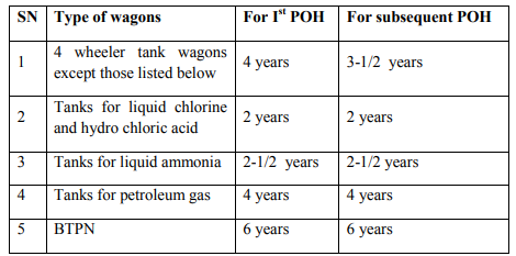
The periodicity of POH is given below:
The codal life of tank wagons is 45 years.
Steam cleaning for pressure vessels, petroleum and other highly inflammable products:
Tanks as pressure vessels, tanks for petroleum, other highly inflammable products, vegetable oils, bitumen, coal tar and molasses are cleaned by steam. The tanks requiring steam cleaning should be placed as near the steam supply line as possible and protected against any movement. The berthing siding should be completely isolated from all other traffic. In case of pressure vessels, it should be ensured that all the gas has been discharged to the atmosphere.
After ensuring that the tank barrel is no longer under pressure, the following sequence should be followed:
Remove the manhole cover together with manhole housing, valves etc. and leave the tank exposed to atmosphere for 24 hours. Entry of staff in the tank barrel should be strictly prohibited and signs with suitable legends displayed at a reasonable distances away from the tanks to be steam cleaned. Insert pipe through manhole and steam the interior of barrel for 12 hours. In order that the tank barrel is thoroughly steamed from inside, the steam pipe should be provided with a “T” connection at its lower end and so directed as to blow steam towards both ends. Remove condensed steam collected in the tank barrel and keep the barrel exposed to atmosphere for another 24 hours.
The following are the tests that should be conducted to ensure the tanks are free from contamination gases of the contents.
AMMONIA TANK BARREL
Fill the tank barrel with water. Collect a specimen of the water in a clean glass bottle. Test the specimen of the water with red litmus paper. If the colour of the litmus paper turns into blue, it indicates that the barrel is still having the gases of ammonia and requires steam cleaning.
NESSLER’S TEST
Test the specimen of the water with a mixture of potassium mercuric iodide and potassium hydroxide. If the colour of the mixture turns into brown, it indicates that the barrel is still having the gases of ammonia and requires steam cleaning
CHLORINE TANK WAGONS
Fill the tank barrel with water. Collect a specimen of the water in a clean glass bottle. Test the specimen of the water with red litmus paper. If there is any bleaching effect on the litmus paper, it indicates that the barrel is still having the gases of chlorine and requires steam cleaning.
LPG TANK WAGONS
Fill fresh water in a clean bottle. A string is to be attached to the bottom of the bottle. Lower the bottle through the manhole up to the bottom of the tank and tilt the bottle. Allow the water to flow out and let the gas get into the bottle. Wait for 5 minutes and lift the bottle and close the mouth immediately after withdrawing. Take it away from the tank. Bring a lighted matchstick near the mouth of the bottle after opening it. If there is no flame it is free from injurious gas. But in case it gives out a flame, the tank should again be steam cleaned again.
Procedure for steam cleaning of bitumen and molasses tank wagons:
Close the manhole cover and open bottom discharge valve. Pass steam through the air inlet valve for sufficient time till the bitumen melts and drains away through the water discharge valve. The bitumen should be collected in containers and not drained out on the floor. Open the manhole cover to see whether the tank is completely cleaned from inside. In case any residue is left behind the above procedure should be repeated. Remove heating arrangement i.e., heating pipe, internal pipe, etc, from the tank. Clean inside surface of the heating pipe by scrapping the carbon layer with wire brush or other suitable process. Blow in air under pressure from one end. The outer surface of the heating pipe should be cleaned with kerosene oil.
Procedure for cleaning of tanks for corrosive liquids:
HYDROCHLORIC ACID TANKS:
Open the manhole and the washout cover and start cleaning the barrel with water. Initially the water coming out of the washout opening will show excessive acidity, which will turn blue litmus paper into red. The washing should be continued till blue litmus paper shows no change. Then close the wash out cover, fill the tank with water. Collect a sample of the water in a bottle. Test the sample of water with blue litmus paper. If the colour is changing to red, it indicates that the tank is still having traces of acid and requires cleaning.
SULPHURIC ACID TANKS:
Wash the Sulphuric acid tank barrels with ½ % to 1% solution of sodium phosphate commercial or half percent solution of soda ash so as to neutralize the sulphuric acid. The washing should be done as soon as it is received in workshops. Since concentrated sulphuric acid absorbs moisture when left open to moist air, the acid will be diluted with time. It is to be remembered that diluted sulphuric acid is highly corrosive and attacks the tank barrel more vigorously. Collect a sample of water in a bottle. Test with blue litmus paper. If the colour of the paper changes into red, it indicates that tank is having still traces of acid and requires cleaning again. After cleaning allow the tank for drying.
Caution: As addition of water to sulphuric acid will produce intense heat, resulting in splashing of steam, the solution of 361 commercial sodium phosphate should be added or spread gradually and with care.
CAUSTIC SODA TANKS:
Wash the barrels with hot water. Freedom from alkalinity can be easily ascertained by litmus test (if red Litmus changes to blue, there are still traces of alkalinity). After it is free from alkalinity, water should be drained and barrel dried before inspection and repairs
Checks to be carried out by the C&W Engineers before the tank wagon is certified for loading
Master Valve: Leakage of master valve should be checked while keeping the bottom discharged valve in open. Bottom discharge
Valve: Proper functioning and fluid tightness of the bottom discharge Valve should be ensured. Blank flange: The blank flange of the correct thickness made out of steel plate and with a gasket of proper material between the blank flange and bottom discharge valve flange should be tightened by six bolts and nuts.
Tank barrel: Tanks with cracks on barrels should be marked sick. Leaky Tank barrels: The leakage of tank barrels may be caused due to the following reasons. Mechanical injury to the valve face and /or valve seat as a result of foreign material, particularly nuts and bolts finding their way inside the tank wagon, valves seat not properly secured to the stool by proper interference fits and malfunctioning of master valve.
Precautions in the case of leakage from the loaded tank wagons:
CHLORINE & AMMONIA tanks;
Chlorine and ammonia gases are poisonous and have a characteristic pungent odour, which gives warning of their presence in the atmosphere before dangerous concentrations are attained. In the case of chlorine, the greenish yellow colour of the gas makes it visible when high concentrations are present. In the case of ammonia, if sufficient concentration of the gas is present in the atmosphere, it will irritate the eyes and the respiratory system.
As such, in the event of leakage, all present in the vicinity should be warned to keep on the windward side of the tank.
HIGHLY INFLAMMABLE GAS tanks;
All the flames or fires near it should be extinguished or removed. Smoking should not be allowed. Spectators should be kept away. Only battery operated torches or incandescent electric lights with gas proof sockets should be used. Oil lanterns or signal lamps used for signalling must be kept away. The steam engine available if any should be moved away from the site. The leaky tank wagon should be removed as quickly as possible to an open area, where the escaping gas will be less hazardous. Earth should be spread over any surface on which the LPG has leaked out in liquid form. Call the company concerned for further attention.
(CTRB) CARTRIDGE TAPERED ROLLER BEARING:
Defects in CTRB:
a) Double cup:
- Stain discoloration, corrosion, pitting and rust.
- Flaking/spilling.
- Beveling.
- Pitting.
- Electric burns.
- Cracks & fractures.
- Decrease in outer diameter.
- Increase in counter bore.
b) Cone assembly:
- Stain discoloration, corrosion, pitting and rust.
- Flaking/spilling.
- Smearing & peeling.
- Wear &tear of lage.
- Pitting marks on roller surface.
- The clearance between cage pocket & roller is more than 1.5mm.
- The clearance between cage flange & inner ring is more than 2.3mm.
- Internal diameter of cage more than 144.4879mm.
c) Wear ring:
- Breakage in contact route of lip.
- Scratches or cracks on out face.
d) Grease seal:
- Hardened, cracked or cut seal lip.
e) Backing ring:
- Pitting marks
- Cracked fractured or heavy corrosion.
- Loose wear ring in counter bore of locking ring.
- Increase internal diameter i.e. more than 178.56mm.
AAR approved grease Qty/ Bearing – 455 +/-30 gms.
Lateral play fixture – 0 .51 to 0.66mm.
Torque for axle end cap – 40 Kgm.
Bearing mounting pressure – 55 +/-5 Ton.
Defects, their cause & remedial action:
CENTRE BUFFER COUPLER
CBC is combined unit of Draw and Buffing Gear, located at the centre of Body Head Stock.
i. Used as Draw Gear.
ii. Used to transmit buffing force.
ADVANTAGES OF CBC:
- Coupler and buffing gear are both located together at the centre of the wagon.
- Coupling action between wagon is automatic so that more safer for operation.
- Hauling capacity increased.
- Maintenance cost is less than conventional Draw gear.
- Hauling capacity of conventional draw gear is- 2200 T
- Hauling capacity of CBC -7000 T to 9000T.
TWO TYPES OF CBC ON THE BASIS OF OPERATION:
i. Transition type CBC.
ii. Straight type CBC. MAIN COMPONENTS OF CBC
A. COUPLER BODY:
i. Coupler head.
ii. Coupler shank.
iii. Coupler tail.
iv. Coupler guard arm.
v. Coupler lock chamber.
vi. Coupler shank wears plate
B. KNUCKLE:
i. Knuckle nose.
ii. Knuckles lock face.
iii. Knuckle front face.
iv. Knuckle thrower / Kicker.
v. Knuckle pin.
C. STRIKER CASTING
D. STRIKER CASTING WEAR PLATE
E. LOCKING PIECE
F. ROTARY LEVER ASSEMBLY
i. lever hook.
ii. lever contraction.
iii. toggle.
G. CBC OPERATING HANDLE
H. CBC OPERATING HANDLE BRACKET
I. CBC OPERATING HANDLE WEAR PIECE
J. YOKE PIN SUPPORT PLATE
K. YOKE SUPPORT PLATE
L. TRANSITION COUPLING
i. Clevis.
ii. Clevis pin.
M. FRONT FOLLOWER N. BACK STOPPER
O. YOKE, YOKE PIN 371
P. DRAFT GEAR
i. HR-40 [ All vacuum brake bogie goods stock]
ii. MK-50[Air brake bogie goods stock]
iii. RF-361[-----------------do---------------]
iv. SL-76 [------------------do-------------]
Q. BEARING PIECE: Size 16 x 16 x 270- mm (Modified) with 16x16x210-mm
1. STANDARD AAR(NHT) COUPLER:
- Broad gauge goods stock
- Used in vacuum brake bogie stock and brake van
- Working capacity-86T.
- Full proof load-132T.
- Braking capacity-251T.
- Hauling capacity in 1:100 up gradient-6500T-7000T.
- Draft gear utilized-HR-40.1.
- Buffing capacity-6200 Kg.
- Long case buffer used with transition CBC.
2. STANDARD AAR (HT) COUPLER:
- Upgraded version of standard AAR coupler.
- Used in air brake broad gauge goods stock.
- Buffer not used since it is a straight CBC type.
- Black color paint.
- Working capacity-120T.
- Full proof load-170T.
- Braking capacity-295T.
- Hauling capacity in 1:100 up gradient-9000T.
- High capacity friction draft gear is used.
TRAIN PARTING
When a train after formation, during run, shunting operation or while starting/ stopping divides itself into two or more parts, is termed as train parting. This is termed as “J” Class Accident In such cases the driver should keep the front portion moving as far as possible until rear portion has stopped to avoid any possibility of collision between the two parts of the train and cause of derailment. Guard should immediately try to stop the rear portion of the train by applying the hand brakes to avoid collision with front portion. Then driver & guard shall act accordingly to provision of G & SR to clear the block section in case of train parting occurred in the block section.
THE REASON OF TRAIN PARTING
Incidence of train parting is an accident as per accident manual. The train parting takes place mainly due to following reasons:-
a) Operational reason: Operational reason such as bad engineman ship by driver Brake binding due to emergency application of the brakes etc also contributes to the train parting. Bad driving technique such as fast notching up of locomotive, sudden application of brakes, bad driving on gradient, improper road knowledge etc. can also contribute to train parting.
b) Due to defective signal: Train parting mostly taking on up gradient followed with down gradient, the most important location where the cases are more is near the home signal which means driver while started from home signal after stopping are not ensuring releasing of brake in shock load on knuckles.
c) Poor Maintenance of P Way Track: Analysis of section wise occurrence of train parting on railway indicates that bad section can be identified and driver should be counselled for pre drive techniques such as poor rail joints, mud accumulated track create uneven height with CBC coupler resulted train parted due to vertical slipping of knuckle.
d) Improper maintenance of rolling stock: Train parting takes place in goods train due to following improper maintenance of rolling stock.
Causes & their remedial action for AAR CBC:
Defects of CBC which leads to Train Parting.
A. Anti rotation lug not available or non standard. (Standard size 270 X 16 X 16mm).
B. CBC operating handle bearing piece slot more wear and tear (Standard size17.5 X 17.5 mm).
C. Wear in lock lifter assembly.
D. CBC operating handle non standard i.e. bent portion length more than 400 mm.
E. Failure on A/C of Commercial Department
F. Miscellaneous
i) Due to handling of operating handle by miscreant
ii) Grassing of operating handle with platform while running.
ACTION TO BE TAKEN BY THE FIELD STAFF: -
1. Parting of train takes place due to breakage of CBC or screw coupling during running of train. This is a dangerous situation for safety of trains therefore precaution to be taken by crew as mentioned below
a) To keep away front portion of train running
On noticing that train has parted, the driver of the train must try to take the front portion of the train as much ahead as possible. This may be done till the rear portion of the train comes to stop. This will avoid any chance of the collision in between both the portion of parted train. For taking ahead the front portion driver may take notches with the permissible amount of traction current.
i) To stop rear portion of the train After noticing the train parting, Guard of the train will apply hand brakes to stop the rear portion of the train as soon as possible.
ii) Exchange of signal 381 After noticing, Driver may confirm the train parting as follows
1. Experiencing sudden drop of air pressure
2. Looking back and finding out that the train is parted in two portions.
i) Re coupling of both portion of the train after stoppage of both portion of train guard of the train should secure the rear portion of load by applying the hand brakes properly. After bringing both portions together the following step to be taken.
ii) Clearing of load in two Portion After parting of train if it is not possible to clear the load in one hook due to damage of CBC or its component, the parted load to be cleared in two portions. Front portion should be cleared by the driver up to next incoming station & rear portion can be attached and cleared with another engine after attaching with rear most wagons. .
9.11 SAB AND LOAD EMPTY BOX
SAB (SVENSKA AKTIE BOLAGOT BROMS Regulator)
This is a mechanical device provided in the brake rigging, and forms part of the pull rod, for automatic adjustment of the clearance between the brake blocks and wheels in the brake rigging. This automatically operates to shorten or lengthen the length of the pull rod, to adjust the excess or less slack in the brake rigging or brake block clearance. This helps to maintain the clearance between the brake block and the wheels to a predetermined constant value always, thereby maintaining the piston stroke of the brake cylinder constant. This, in turn, always maintains constant brake power for the wagon or coach on the run.
Types of SAB
i. DRV 450
ii. DRV 600

Main parts of the SAB
1. Adjuster Spindle
2. Leader Nut
3. Adjuster Nut
4. Traction sleeve
5. Barrel
6. Adjuster Tube
7. Barrel Spring
9. Take up Spring
10. Pay out Spring
11. Adjuster Ear
12. Control Rod Head
13. Control rod
Control “A” Dimension
This is the distance between the slack adjuster barrel and the control rod head, measured when the brake is in fully released condition.

This is called as ‘Control Dimension’, because this is the pre-determined dimension, according to which the slack adjuster pays-out /takes-up the slack in the brake rigging.
The control rod ‘A’ dimension for Different Rolling stock is given below.

‘e’ Dimension
This is the distance between the end of the protective sleeve of the screw and the grooved mark on the screw rod when the brake is fully released

This indicates the total capacity of the slack adjuster available for the adjustment of the brake rigging clearance. This dimension will be 375±25 mm for coaching stock and 555±20 mm for goods stock. It will decrease as wear takes place on brake a) Coaching stock 16+ 2/ -0mm for 13 T Bogie stock 22+ 2/ -0 mm for 16.25 T bogie stock 22+ 4/-0 mm for Air Brake Stock (HS) b) Goods Stock 50 mm for VB Stock 70 mm for Air brake stock 27 mm for BOBRN blocks, wheels, brake gear pins and bushes due to brake applications. And it will be the maximum when all Brake blocks, brake gear pins and bushes are new and all the wheels are at maximum diameter.
As the ‘e’ dimension decreases and reaches to the minimum due to the wear on the wheel tread, which cannot be made up (worn out brake blocks, brake gear pins and bushes can be replaced with new ones), manual adjustment shall be done according to the worn out wheel diameter, on the adjusting link of the bogie. This will ensure that sufficient capacity of ‘e’ dimension will be again made available for subsequent adjustments.
Functioning of the SAB:
The SAB is working based on the principle of LIMITING FRICTION. Due to this Limiting friction, the nuts that are provided inside the SAB get rotated automatically, whenever the excessive forces offered due to the incorrect slack acting on them. The rotation of these nuts on the screw rod causes the screw rod to move inward or outward for increasing or decreasing the length of pull rod till the correct adjustment of piston stroke and clearance is obtained.
Adjustment of control ‘A’ dimension. Assemble the slack adjuster (SAB brake regulator) on the bogie brake rigging. Ensure that the hand brake and brake cylinders and the rigging are in fully released condition and in proper working order. Apply and release the brakes few times and again ensure that the brake rigging is in fully released condition. Check the ‘A’ dimension, if found correct, secure the pins correctly.

If found more, disconnect the control rod from its bracket and lengthen it by rotating anti-clockwise. If found less, shorten its length by rotating it clock-wise.

One full rotation of the control rod will alter the ‘A’ dimension by 2 mm. Fix the control rod in its bracket and apply and release the brakes few times, check ‘A’ dimension, adjust it if required and test. Secure the pin when correct.
‘A’ Dimension to be correctly set to maintain the correct piston stroke and in turn the correct brake power. Rotating the SAB or slack adjuster barrel will not alter the ‘A’ dimension. Once set correctly shall not alter it during service.
Take –Up and Pay-Out Test of SAB
For testing the slack adjuster, it need not be removed from the bogie brake rigging. It can be tested as it is on the bogie, during pit-line examination as follows. Make few brake applications and release and note the piston stroke.
Take-up test: Rotate the barrel anticlockwise 2 or 3 times, to increase the brake block clearances. Apply the brake and release.

Note the higher piston stroke, at first application.
Apply and release the brakes. The stroke will be normal (equal to the original piston stroke) after 3 or 4 applications. This shows take up is satisfactory, If not slack adjuster is defective
Pay-out test: Rotate the barrel 2 or 3 times clockwise to decrease the brake block clearance. Apply the brake and release.

Note the short piston stroke at the first application. The stroke will be normal (equal to the original piston stroke) after 3 or 4 applications. This shows Pay-out is satisfactory. If not the slack adjuster (SAB) is defective.
Empty-Load Device It is a mechanical device, which enables to provide two different leverage ratios to the brake rigging of the wagon for the empty and the loaded conditions

The braking force required to stop a train within the permissible stopping distance depends on the load of the train. As the load increases, more brake power is required, and as the load decreases, less brake power is required to stop the train. So the brake power should be increased or decreased according to the requirement by changing the brake leverage ratio. To enable this, the ‘EMPTY-LOAD BOX’ device is provided on wagons, in between the brake cylinder and the brake blocks in the brake rigging. The position of the change over lever of the E/L Box is to be set to ensure correct brake power according to the gross weight, as given below.
Less than 42.5 tonnes – in empty position
42.5 tonnes &above - in loaded position Brake
The LOAD-EMPTY device consists of two horizontal levers (one live and the other dead) and are connected by means of empty and load tie rods. When the handle is kept in empty position, the empty tie rod is connected with the system and in turn provides low leverage ratio, thereby gives lesser brake force. When the handle is kept in load position, the load tie rod is connected with the system and in turn provides higher leverage ratio, there by gives higher brake force as required.
Resetting of Empty/Load box:
Release brake rigging completely, including the release of hand brake fully. Ensure horizontal levers can move freely. Keep change over lever in ‘load’ position. Shift lock nuts and washers of sleeve nut as far as possible.

Rotate sleeve nut and tighten empty tie rod fully. Then rotate sleeve nut slowly in reverse direction to lengthen empty tie-rod. Stop rotating as soon as the end of the “live horizontal lever” starts moving.

Carry out test
Tighten lock – nuts and bend lock washers.
Testing the Load-Empty device for its effective functioning
Keep the change over lever in ‘empty’ position, a clear click sound should be heard. Apply the brake and tap the empty tie rod pins, it should be tight. Tap the load tie rod pins, they should be loose. If tight, the adjustment is wrong, and indicates the sleeve nut might have been tampered with.
Release the brake and keep the change over lever in load position and apply brake. Tap the load tie rod pins, they should be tight. Tap the empty tie rod pins, they should be loose. If not adjust the empty tie rod as given above.
- CBC back stoppers plate broken and / or its rivet missing.
- Draft support plate rivet loose.
- CBC yoke cracked / broken.
- CBC yoke pin support plate rivet loose.
- Lock seat worn out or lug broken.
- Excessive wear on lock piece.
- Articulated lock lift assembly missing. CBC Drooping due to CBC shank wear plate excessively worn out.
- Excessive wear on knuckle nose.
- Cracked knuckle.
- Wear in anti creep device.
A. Anti rotation lug not available or non standard. (Standard size 270 X 16 X 16mm).
B. CBC operating handle bearing piece slot more wear and tear (Standard size17.5 X 17.5 mm).
C. Wear in lock lifter assembly.
D. CBC operating handle non standard i.e. bent portion length more than 400 mm.
E. Failure on A/C of Commercial Department
- Over-Loading (Beyond carrying capacity) :If any particular wagon is over-loaded beyond its carrying capacity will lead to difference in buffer height between two wagons (more than 75 mm), it may cause disengagement of knuckle in locked condition i.e. vertical slipping of knuckles.
- Un-Even Loading: Due to un-even loading of any particular wagon it may lead to uneven CBC height on either end of the wagon & may cause in train parting.
F. Miscellaneous
i) Due to handling of operating handle by miscreant
ii) Grassing of operating handle with platform while running.
ACTION TO BE TAKEN BY THE FIELD STAFF: -
1. Parting of train takes place due to breakage of CBC or screw coupling during running of train. This is a dangerous situation for safety of trains therefore precaution to be taken by crew as mentioned below
a) To keep away front portion of train running
On noticing that train has parted, the driver of the train must try to take the front portion of the train as much ahead as possible. This may be done till the rear portion of the train comes to stop. This will avoid any chance of the collision in between both the portion of parted train. For taking ahead the front portion driver may take notches with the permissible amount of traction current.
i) To stop rear portion of the train After noticing the train parting, Guard of the train will apply hand brakes to stop the rear portion of the train as soon as possible.
ii) Exchange of signal 381 After noticing, Driver may confirm the train parting as follows
1. Experiencing sudden drop of air pressure
2. Looking back and finding out that the train is parted in two portions.
i) Re coupling of both portion of the train after stoppage of both portion of train guard of the train should secure the rear portion of load by applying the hand brakes properly. After bringing both portions together the following step to be taken.
- Intimation to section controller about paring of train
- After coupling of both CBC’s there should be no gap (lock should proper engage)
- Connection of air hoses and preparation of pressure
- Conduct continuity test.
- Start the train to reach up to next station
- Repeat the case to station master/SCOR in following details
- Engine Number
- Train load
- Driver’s & Guard’s Name.
- Location of wagon evolved in train parting.
- BPC issuing station and date.
- Kilometer on track.
- Condition of gradient.
- Train parting and load coupling time
- Wagon particulars.
- Probable cause of train parting etc.
ii) Clearing of load in two Portion After parting of train if it is not possible to clear the load in one hook due to damage of CBC or its component, the parted load to be cleared in two portions. Front portion should be cleared by the driver up to next incoming station & rear portion can be attached and cleared with another engine after attaching with rear most wagons. .
9.11 SAB AND LOAD EMPTY BOX
SAB (SVENSKA AKTIE BOLAGOT BROMS Regulator)
This is a mechanical device provided in the brake rigging, and forms part of the pull rod, for automatic adjustment of the clearance between the brake blocks and wheels in the brake rigging. This automatically operates to shorten or lengthen the length of the pull rod, to adjust the excess or less slack in the brake rigging or brake block clearance. This helps to maintain the clearance between the brake block and the wheels to a predetermined constant value always, thereby maintaining the piston stroke of the brake cylinder constant. This, in turn, always maintains constant brake power for the wagon or coach on the run.
Types of SAB
i. DRV 450
ii. DRV 600
Main parts of the SAB
1. Adjuster Spindle
2. Leader Nut
3. Adjuster Nut
4. Traction sleeve
5. Barrel
6. Adjuster Tube
7. Barrel Spring
9. Take up Spring
10. Pay out Spring
11. Adjuster Ear
12. Control Rod Head
13. Control rod
Control “A” Dimension
This is the distance between the slack adjuster barrel and the control rod head, measured when the brake is in fully released condition.
This is called as ‘Control Dimension’, because this is the pre-determined dimension, according to which the slack adjuster pays-out /takes-up the slack in the brake rigging.
The control rod ‘A’ dimension for Different Rolling stock is given below.
‘e’ Dimension
This is the distance between the end of the protective sleeve of the screw and the grooved mark on the screw rod when the brake is fully released
This indicates the total capacity of the slack adjuster available for the adjustment of the brake rigging clearance. This dimension will be 375±25 mm for coaching stock and 555±20 mm for goods stock. It will decrease as wear takes place on brake a) Coaching stock 16+ 2/ -0mm for 13 T Bogie stock 22+ 2/ -0 mm for 16.25 T bogie stock 22+ 4/-0 mm for Air Brake Stock (HS) b) Goods Stock 50 mm for VB Stock 70 mm for Air brake stock 27 mm for BOBRN blocks, wheels, brake gear pins and bushes due to brake applications. And it will be the maximum when all Brake blocks, brake gear pins and bushes are new and all the wheels are at maximum diameter.
As the ‘e’ dimension decreases and reaches to the minimum due to the wear on the wheel tread, which cannot be made up (worn out brake blocks, brake gear pins and bushes can be replaced with new ones), manual adjustment shall be done according to the worn out wheel diameter, on the adjusting link of the bogie. This will ensure that sufficient capacity of ‘e’ dimension will be again made available for subsequent adjustments.
Functioning of the SAB:
The SAB is working based on the principle of LIMITING FRICTION. Due to this Limiting friction, the nuts that are provided inside the SAB get rotated automatically, whenever the excessive forces offered due to the incorrect slack acting on them. The rotation of these nuts on the screw rod causes the screw rod to move inward or outward for increasing or decreasing the length of pull rod till the correct adjustment of piston stroke and clearance is obtained.
Adjustment of control ‘A’ dimension. Assemble the slack adjuster (SAB brake regulator) on the bogie brake rigging. Ensure that the hand brake and brake cylinders and the rigging are in fully released condition and in proper working order. Apply and release the brakes few times and again ensure that the brake rigging is in fully released condition. Check the ‘A’ dimension, if found correct, secure the pins correctly.
If found more, disconnect the control rod from its bracket and lengthen it by rotating anti-clockwise. If found less, shorten its length by rotating it clock-wise.
One full rotation of the control rod will alter the ‘A’ dimension by 2 mm. Fix the control rod in its bracket and apply and release the brakes few times, check ‘A’ dimension, adjust it if required and test. Secure the pin when correct.
‘A’ Dimension to be correctly set to maintain the correct piston stroke and in turn the correct brake power. Rotating the SAB or slack adjuster barrel will not alter the ‘A’ dimension. Once set correctly shall not alter it during service.
Take –Up and Pay-Out Test of SAB
For testing the slack adjuster, it need not be removed from the bogie brake rigging. It can be tested as it is on the bogie, during pit-line examination as follows. Make few brake applications and release and note the piston stroke.
Take-up test: Rotate the barrel anticlockwise 2 or 3 times, to increase the brake block clearances. Apply the brake and release.
Note the higher piston stroke, at first application.
Apply and release the brakes. The stroke will be normal (equal to the original piston stroke) after 3 or 4 applications. This shows take up is satisfactory, If not slack adjuster is defective
Pay-out test: Rotate the barrel 2 or 3 times clockwise to decrease the brake block clearance. Apply the brake and release.
Note the short piston stroke at the first application. The stroke will be normal (equal to the original piston stroke) after 3 or 4 applications. This shows Pay-out is satisfactory. If not the slack adjuster (SAB) is defective.
Empty-Load Device It is a mechanical device, which enables to provide two different leverage ratios to the brake rigging of the wagon for the empty and the loaded conditions
The braking force required to stop a train within the permissible stopping distance depends on the load of the train. As the load increases, more brake power is required, and as the load decreases, less brake power is required to stop the train. So the brake power should be increased or decreased according to the requirement by changing the brake leverage ratio. To enable this, the ‘EMPTY-LOAD BOX’ device is provided on wagons, in between the brake cylinder and the brake blocks in the brake rigging. The position of the change over lever of the E/L Box is to be set to ensure correct brake power according to the gross weight, as given below.
Less than 42.5 tonnes – in empty position
42.5 tonnes &above - in loaded position Brake
The LOAD-EMPTY device consists of two horizontal levers (one live and the other dead) and are connected by means of empty and load tie rods. When the handle is kept in empty position, the empty tie rod is connected with the system and in turn provides low leverage ratio, thereby gives lesser brake force. When the handle is kept in load position, the load tie rod is connected with the system and in turn provides higher leverage ratio, there by gives higher brake force as required.
Resetting of Empty/Load box:
Release brake rigging completely, including the release of hand brake fully. Ensure horizontal levers can move freely. Keep change over lever in ‘load’ position. Shift lock nuts and washers of sleeve nut as far as possible.
Rotate sleeve nut and tighten empty tie rod fully. Then rotate sleeve nut slowly in reverse direction to lengthen empty tie-rod. Stop rotating as soon as the end of the “live horizontal lever” starts moving.
Carry out test
Tighten lock – nuts and bend lock washers.
Testing the Load-Empty device for its effective functioning
Keep the change over lever in ‘empty’ position, a clear click sound should be heard. Apply the brake and tap the empty tie rod pins, it should be tight. Tap the load tie rod pins, they should be loose. If tight, the adjustment is wrong, and indicates the sleeve nut might have been tampered with.
Release the brake and keep the change over lever in load position and apply brake. Tap the load tie rod pins, they should be tight. Tap the empty tie rod pins, they should be loose. If not adjust the empty tie rod as given above.


