DIESEL LOCO - Dynamic Braking
Advantages of dynamic braking
1. No wear and tear in brake block and wheels.
2. Speed of train can be maintained constant on down gradient.
3. Train can be controlled easily with out jerk.
4. Fuel saving.
5. To Maintain train punctuality.
Procedure of Applying Dynamic Brake –
1. Bring MH to idle position gradually.
2. Apply train brake by A9.
3. Bring MH on IDLE’ position and then SH kept on “Braking” position. After this MH kept on “o” and then braking position and wait for some time, then move the master handle slowly towards the‘MAX’ positions of braking.
4. Keep watch on load meter.
5. To release the dynamic brake, bring the MH slowly to “Braking” position and then “o” position.
6. After waiting for some time, MH handle kept on “Idle” Position and then SH kept on “Motoring” position.
Precautions to be taken During Dynamic Braking -
1. Operate the master handle smoothly.
2. Do not apply independent loco brakes during Dynamic Brake.
3. Do not apply emergency train brakes.
4. Do not apply dynamic brakes when BKBL is not working
5. During dynamic braking if GR operates, don’t apply dynamic brakes.
6. If GFC is wedge do not use dynamic brake.
7. If the locomotive speed exceeds more than 90 km/h, braking current should not exceed 600 amps. 8. If the speed of the locomotive is less than 90 km/h then - Maximum braking current is limit up to 800 amps.
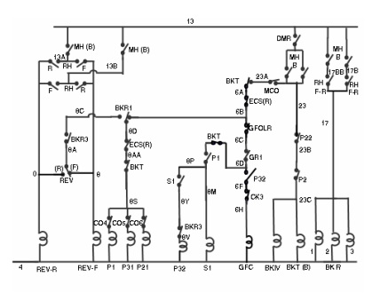
Changes take place during Dynamic Braking –
1. BKT position will change to braking.
2. BKR1, 2, 3 energized.
3. The loco brakes applied in conjunction braking will be released due to D1 pilot valve energized.
4. GFC will picks up.
5. Engine RPM increases to 4th notches RPM.
6. Reverser coil energize.
7. All power contactors will pick up except P2, P22, S21 and S31 due to which following changes takes place.
a) All TM field coil will be connected in series across the Traction Alternator and get excitation current.
b) All TM armatures will be in group of two and connected across the braking grids.
c) All TM will work as separately excited generator and generated current goes to braking grids and BKBL. BKBL cools the braking grids.
d) Retardation torque produced in TM which opposed the wheel movement.