
LUBE OIL SYSTEM
Purpose -To lubricate and cool the diesel engine equipment with filtered, cooled and pressurized lube oil.
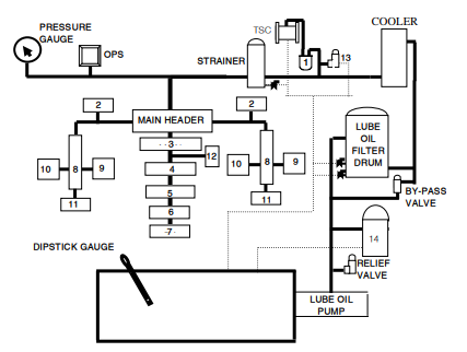
Description – Forced lubrication system is used in diesel locomotive, detail of system is as -
Lower portion of engine crank case, it termed as lube oil sump, its capacity is 1210 litters. To fill the lube oil filling cap is provided on free end engine right side. Dipstick gauge is provided near R5 cylinder for measuring lube oil level. Dipstick gauge having 0-600 litters marking each mark of 20 litters. While checking lube oil level engine should be on idle condition and crank case exhauster motor should be in ON position.
Lube oil pump is "Positive displacement type" and located in engine room right side free end. It gets drive from main crank shaft extension shaft no. 1 gear. When diesel engine starts, lube oil pump also starts working; it sucks oil from the sump and sends to delivery pipe, on delivery pipe relief valve (setting 9.5 kg/cm2) is provided. Oil from delivery pipe goes to filter drum & centrifugal filter. After filtration of oil from centrifugal filter return to sump and oil from filter drum goes to system for lubrication
Filter Drum has two zones, filtered and unfiltered. Each zone having separate drain cock it should be tied and sealed. One by pass valve (setting 20psi differential pressure) is provided near filter drum, it by pass filter drum at the time of engine starting or when filter is chock up. Filtered oil from lube oil filter drum goes to lube oil cooler, it is located in radiator room here oil gets cool with water tubes. Out going pipe of lube cooler has regulating valve (setting 5.2 kg/cm2). Before this valve one connection given to TSC through micro filter to lubricate bearing in intermediate casing.
The oil coming from lube cooler goes to lube oil strainer (location engine room left side), strainer has one drain cock it should be tied and sealed. From strainer filtered oil goes to main header (location in lube oil sump).
Main header having 9 S-type jumper pipes and each pipe is connected to main bearing. After lubricating main bearing oil goes to crank pin and lubricates connecting rod bearing. Through connecting rod oil goes to piston pin and lubricated it and also cools the piston crown, further oil dropped in the sump through return passage, while dropping oil splash and lubricate the cylinder liners.
Two pipe connections were given from main header to sub header and one ‘T’ joint on each pipe given for cam shaft, which helps in lubricating cam shaft bearings. From both sub header two pipe
connections are provided for each cylinder to lubricate rocker arm assembly and fuel pump lifter. At the end of both sub header on power take off end one nozzle is provided to lubricate cam shaft gear as well as split gear in spray form.
From main bearing no. 1 oil goes to vibration damper, it reduces the main crank shaft vibrations.
From main header one connection given to lube oil pressure gauge and oil pressure switch in loco pilot cab.
From main bearing no. 1 oil goes to vibration damper, it reduces the main crank shaft vibrations.
From main header one connection given to lube oil pressure gauge and oil pressure switch in loco pilot cab.
1-MICRO FILTER
6-PISTON CROWN
11-SPRAY NOZZLE
2- CAM SHAFT BEARINGS
7-CYLINDER LINER
12- VIBRATION DEMPER
3-MAIN BEARINGS
8.SUB HEADER
13- RELUGULATING VALVE
4- CRANK PIN 9. ROCKER ARM ASSEMBLY
14- CENTRIFUGAL FILTER 5-PISTON PIN 10. FIP LIFTER
6-PISTON CROWN
11-SPRAY NOZZLE
2- CAM SHAFT BEARINGS
7-CYLINDER LINER
12- VIBRATION DEMPER
3-MAIN BEARINGS
8.SUB HEADER
13- RELUGULATING VALVE
4- CRANK PIN 9. ROCKER ARM ASSEMBLY
14- CENTRIFUGAL FILTER 5-PISTON PIN 10. FIP LIFTER
Crank case exhauster motor- It is located on engine left side power take off end. Initially it starts on battery further it work on auxiliary generator out put. A blower is fitted on its shaft which creates partial vacuum and evacuated gasses from crank case sump. Working of motor is confirmed from its indication lamp provided on both control desks. If CCM not work, find the causes if not successes clear the section and fail the loco.
Crank case explosion door- Due to any reason if pressure of the gasses in side the engine block is increased which leads to damage engine block.To avoid the damage crank case explosion doors are provided. When pressure increased more than prescribed level explosion door gets burst and safe guard the engine block. On each side of crank case one spring loaded type explosion door is provided in place of crank case cover (normally on R7, L2). When explosion door is burst, gasses come out along with lube oil but due to spring action the door sets on its normal position. In this situation shut down the engine and crank case exhauster motor should be kept on and fail the loco.
Crank case explosion door- Due to any reason if pressure of the gasses in side the engine block is increased which leads to damage engine block.To avoid the damage crank case explosion doors are provided. When pressure increased more than prescribed level explosion door gets burst and safe guard the engine block. On each side of crank case one spring loaded type explosion door is provided in place of crank case cover (normally on R7, L2). When explosion door is burst, gasses come out along with lube oil but due to spring action the door sets on its normal position. In this situation shut down the engine and crank case exhauster motor should be kept on and fail the loco.
CCM not working

Lube oil level increasing in lube oil sump -
Two reasons of lube oil increasing in the sump are
1. Water is mixing in lube oil - Check CCM exhaust pipe if steam/drop Of water coming, its means water is mixing in lube oil. Shut down the engine, fail the loco and inform PCOR.
2. Fuel oil mixing in lube oil - Fuel oil smell will come on lube oil dipstick gauge; it means fuel oil mixing in lube oil. Inform PCOR.

