
Engine starting circuit
Traction alternator armature shaft is connected to main crank shaft with the help of flange joint. On the other end of Traction alternator armature shaft bull gear is fitted. This bull gear is massed with auxiliary generator and exciter generator gear. Rotation of main crank shaft by auxiliary generator and exciter generator is called engine cranking. Auxiliary generator and exciter generator works as motor at the time of engine cranking and when fuel combustion starts in the cylinder then engine will start for this purpose the engine starting circuit provided.
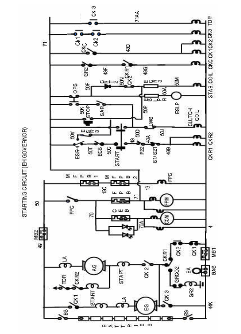
Description of engine starting circuit (EH Gov.) –
1. Close the battery knife switch, battery +ve connect to wire no. 49 and –ve to 44K.
2. Put ON MB1 on the front panel, supply of wire no. 44K goes to wire no 4 through BAS and MB1. 3. Put ON MB2 on front panel, supply of wire no. 49 goes to wire no 50. Due to supply in wire no. 50 and 4, any light will glow on switching ON its concern switch except Dome light.
4. Put ON MFPB1 on left control stand. Supply of wire no. 50 goes to wire no. 13C then put ON MFPB2 on right control stand, supply of wire no 13C goes to wire no 13.
a) FPC coil will be energized by wire no 13 +ve and 4 –ve.
b) When FPC picked up then supply of wire no. 50 goes to wire no.70, CCM indication lamp, wire no. 70A, CCM field winding, wire no.4 and completes the circuit, CCM indication lamp will glow on both control stands.
c) Electric brake warning (PCS) lamp will glow on both control stands.
5. Put ON CEB on front panel, supply of Wire no 70 directly goes to wire no. 70A due to which CCM indication lamp will extinguish and CCM motor will start. When CCM motor fails CCM failure lamp will glow.
6. Put ON FPB on front control panel. Supply of wire no. 70 goes to wire no. 71 due to which fuel pump motor will start; fuel oil pressure will build up to 4.2 kg/cm2. The governor pump also gets start by FPM and governor oil pressure build up to 135 psi. Supply of wire no. 71 goes through OPS NCI (71-50F), CRT2, CK2 NCI (50N-50P), and ECR3 to governor stabilizing coil. Stabilizing action will taken place due to which position of LCR and SP will be changed. Supply of wire no. 50 F goes to ESLP through ESLPR; wire no. 50 AC and 4, ESLP will glow.
7. On pressing Start Button –
a) Supply of wire no. 71 goes to governor clutch coil through start button contact (71-50D), LWS NCI (50D-50J) and coil gets energizes, due to which arm A and B of governor will magnetically locked.
b) Due to closing of other contact of start button (50C-43) Supply of wire no. 71 goes to CK1 coil through ESR4 NCI (71-50T), ECS Idle (50T-50C), start button contact (50C-43), P22 NCI (43-43A), S1 NCI (43A-43B) and CKR1 and CKR2 coil get energizes.
When CKR1 picks up –
1. Exciter generator field is isolated from armature.
2. GR2 comes in service.
3. CKC picks up.
When CKR2 picks up Auxiliary generator field disconnected from armature.
Due to CKC contact CK1, CK2 will pick up.
When CK1 and CK2 picked up their NOI will be close on branch of CK3 coil due to which CK3 coil get energizes.
When CK2 picks up its NCI (50N-50P) will be open on stabilizing coil branch then this coil will de-energized. Magnetically locked Arm A and arm B of Governor moves towards full fuel position due to which fuel supply in cylinder will be start.
8. When CK1, CK2 and CK3 picked up then supply of battery goes to auxiliary generator and exciter generator and it starts to rotate as a motor. The main crank shaft gets drive from auxiliary generator and exciter generator. This is called engine cranking. Due to engine cranking and starting of fuel supply in engine cylinder according to firing order, engine will start with its own power. It is called engine starting.
When engine speed increases up to 280 rpm then SAR gets supply from TG due to which it’s NOI (50K-50D) will be closed on the branch of governor clutch coil. When lube oil pressure builds up to 1.6 kg/cm2 OPS will pick up, its NOI (71-50K) will be closed and NCI (71-50F) will be opened. Due to opening OPS NCI, ESLP will extinguish. After releasing of start button supply of governor clutch coil is maintained by NOI of SAR and OPS, due to which clutch coil remain energized. And CKR1, 2, CKC, CK1, CK2 and CK3 will be drop.
9. Engine will run till governor clutch coil is energized.
Engine Stopping circuit (EH and GE Gov.)-
By pressing the stop button current of wire no.71 goes to wire no.50M through stop button contact wire no.50P-ECR3 resistance, due to which the stabilizing coil will energize, fuel rack comes to zero and engine will shut down.
Engine starting circuit (WW Gov.)
Traction alternator armature shaft is connected to main crank shaft with the help of flange joint. On the other end of Traction alternator armature shaft bull gear is fitted. This bull gear is massed with auxiliary generator and exciter generator gear. Rotation of main crank shaft by auxiliary generator and exciter generator is called engine cranking. Auxiliary generator and exciter generator works as motor at the time of engine cranking and when fuel combustion starts in the cylinder then engine will start for this purpose the engine starting circuit provided.
Description of engine starting circuit –
1. Close the battery knife switch, battery +ve connect to wire no. 49 and –ve to 44K.
2. Put ON MB1 on the front panel, supply of wire no. 44K goes to wire no 4 through BAS and MB1.
3. Put ON MB2 on front panel, supply of wire no. 49 goes to wire no 50. Due to supply in wire no. 50 and 4, any light will glow on switching ON its concern switch except Dome light.
4. Put ON MFPB1 on left control stand. Supply of wire no. 50 goes to wire no. 13C then put ON MFPB2 on right control stand, supply of wire no 13C goes to wire no 13.
a) FPC coil will be energized by wire no 13 +ve. and 4 –ve.
b) When FPC picked up then supply of wire no. 50 goes to wire no.70, CCM indication lamp, wire no. 70A, CCM field winding, wire no.4 and completes the circuit, CCM indication lamp will glow on both control stands.
c) Electric brake warning (PCS) lamp will glow on both control stands.
5. Put ON CEB on front panel, supply of Wire no 70 directly goes to wire no. 70A due to which CCM indication lamp will extinguish and CCM motor will start. When CCM motor fails CCM failure lamp will glow.
6. Put ON FPB on front control panel. Supply of wire no. 70 goes to wire no. 71 due to which fuel pump motor will start; fuel oil pressure will build up to 4.2 kg/cm2.
7. Put ON MCB1&2.
8. Press the alarm push button three times on front panel.
9. On pressing Start Button –
a) Supply of wire no. 71 goes to CKR1 and CKR2 coil through BSR NCI, ECS (I), P22 NCI, and S1 NCI through start button contact. CKR1 and CKR2 will pick up.
b) When CKR1 picks up –
1. Exciter generator field is isolated from armature.
2. GR2 comes in service.
3. CKC picks up.
c) When CKR2 picks up Auxiliary generator field disconnected from armature.
d) Due to CKC contact CK1, CK2 will pick up. When CK1 and CK2 picked up their NOI will be close on branch of CK3 coil due to which CK3 coil get energizes.
e) When CK3 picks up TDR will pick up.
f) When CK1, CK2 and CK3 picked up then supply of battery goes to auxiliary generator and exciter generator and it starts to rotate as a motor. The main crank shaft gets drive from auxiliary generator and exciter generator. This is called engine cranking. Due to engine cranking and starting of fuel supply in engine cylinder according to firing order, engine will start with its own power. It is called engine starting.
When lube oil pressure build up 1.6kg/cm2 then release start button. CKR1, CKR2, CKC, CK1, CK2, CK3 and TDR will drop. Engine will run on its own power.
Engine Stopping circuit (WW Gov.) -
By pressing the stop button its contact (16C-16E) opens on the branch of ERR due to which ERR will de-energize and it’s NCI (50T-3A) close on D valve branch.
The other contact of stop button (71-50T) gets close and current of wire no.71 goes to wire no.3A through wire no.50T, ERR (NCI) due to which only D valve will energize, fuel rack comes to zero and engine will shut down.

Engine starting procedure: Before engine starting check the locomotive (safety fittings, oiling points, water level, etc.) and ensure wooden wedge & hand brake in applied condition. Then start the Diesel engine by following sequence -
1. Put ON Dome light breaker and Dome light switch. Indication - Dome light will glow.
2. Close the BS in Nose room. Indication - AGFL lamp will glow on both control stands.
3. Put ON MB1 on front panel.
4. Put ON MB2 on front panel. Indication - No indication but any light will glow on switching ON its concern switch except Dome light.
5. Put ON MFPB1 on left control stand.
6. Put ON MFPB2 on right control stand. Indication
a) FPC will pick up.
b) CCM indication lamp will glow on both control stands.
c) Electric brake warning (PCS) lamp will glow on both control stands.
7. Put ON CEB on front panel.
Indication - CCM indication lamp will extinguish and CCM motor will start to work.
8. Put ON FPB on control panel. Indication -
Fuel pump motor will start and fuel oil pressure gauge shows 4.2 kg/cm2.
9. Put ON MCB1&2.
10. Press the alarm push button three times on front panel for ringing bell.
11. Put MUSD1, 2 on RUN and ECS on IDLE.
12. Press the Start Button -
a) CKR1 and CKR2 will pick up.
b) CKC will pick up.
c) CK1, CK2 will pick up.
d) CK3 will pick up.
e) TDR will pick up
f) Engine will crank. When lube oil pressure builds up to 1.6 kg/cm2, then release start button.
13. Put ON AGFB on front panel.
Engine stopping procedure
1. Secure the Loco.
2. Keep MH handle on Idle and reverser handle in neutral.
3. Keep ECS on Idle position.
4. Ensure that all CB are ON.
5. Press stop button, till main crank shaft will stop.
Engine is not cranking Before
Engine cranking fuel oil pressure to be checked. If fuel oil pressure is not available, check its reason. If fuel oil pressure is available check following items.

Engine starting procedure with weak battery
If cranking contactors are chattering at time of engine starting, it means battery is weak. In this condition three persons are required to start the diesel engine. One will press start button, second will take manual control of cranking contactor and third will take manual control of governor linkage.
Engine shutdown without indication –
1. OSTA tripped
2. Fuel oil pressure is less/ zero.
3. Shut down plunger of WW governor came out
4. SAR defective
5. MB2/MFPB1/MFPB2/FPB breaker tripped
6. Emphenol plug of EH governor may be loose or uncouple
7. Governor linkage pin may be un couple
8. In sufficient oil in governor
9. When Loco works on battery, if MB1 tripped or battery voltage dropped below 50 volt


